


Quick Research
Generate reliable direction feasibility study reports for your R&D in just a few steps.

Technical Q&A
Discover and master advanced knowledge NOW. Basics, ideas, possibilities, all at once.

Find Solutions
As an expert in R&D theories, this can generate solutions to your technical problems instantly.

Evaluate Feasibility
Analyze your overall solution with one click, know your potential R&D risks in advance.

Monitor Landscape
Get weekly tech updates, stay abreast of the latest tech innovations and key insights.
Wheeled leg robot and driving method thereof
A wheel-legged robot and thigh technology, which is used in motor vehicles, transportation and packaging, etc., can solve the problems of system power loss, complex system composition, and small output torque of joint drive devices.
- Summary
- Abstract
- Description
- Claims
- Application Information
AI Technical Summary
Problems solved by technology
Method used
Image

Examples
Embodiment 1
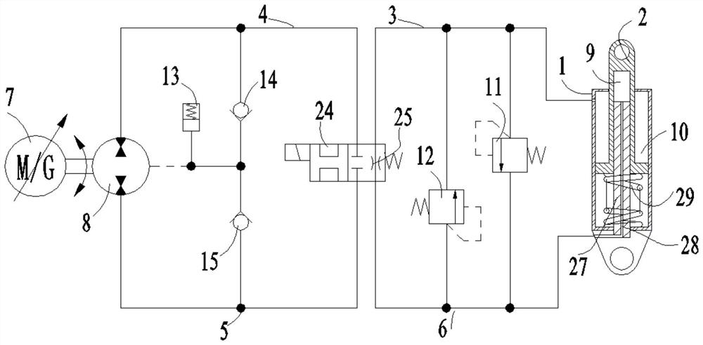
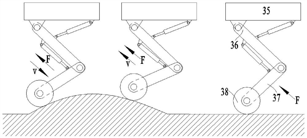
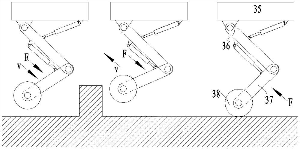
[0030] See attached Figure 1~3. A wheel-legged robot comprises a car body 35, a thigh 36, a calf 37, a wheel 38 and two hydraulic control systems; one end of the thigh 36 is hinged to the car body 35, and the other end of the thigh 36 is hinged to one end of the calf 37; the calf The other end of 37 is provided with a wheel 38; the two hydraulic control systems respectively control the size of the angle between the car body 35 and the thigh 36, and the size of the angle between the thigh 36 and the calf 37; the hydraulic control system includes a hydraulic cylinder 1 and the piston rod 2; the hydraulic cylinder 1 is provided with a bearing chamber 9, a non-bearing chamber 10 and a spring 29; the piston rod 2 separates the bearing chamber 9 and the non-bearing chamber 10; the spring 29 is used to make the piston rod The rod portion of 2 has a tendency to protrude from hydraulic cylinder 1. As can be seen from the above structure, the car body 35 is the body part of the wheel...
Embodiment 2
[0032] See attached Figure 1~3 . On the basis of Embodiment 1, the hydraulic control system also includes a main oil circuit, a secondary oil circuit, a servo motor 7 and a hydraulic pump 8; the servo motor 7 is used to drive the hydraulic pump 8; the non-bearing chamber 10, The main oil circuit, the hydraulic pump 8, the secondary oil circuit and the bearing chamber 9 are connected in sequence; the elongation of the piston rod 2 relative to the hydraulic cylinder 1 changes with the change of the hydraulic oil capacity in the bearing chamber 9 and the non-bearing chamber 10 . It can be seen from the above structure that if the circuit formed by the non-bearing chamber 10, the main oil circuit, the hydraulic pump 8, the secondary oil circuit and the bearing chamber 9 is connected in sequence, the servo motor 7 will rotate forward, and the hydraulic oil in the bearing chamber 9 will be pumped by the hydraulic pump. 8 is sucked to the non-bearing cavity 10, the elongation of t...
Embodiment 3
[0041] See attached Figure 1~3 . A method for driving a wheel-legged robot, using the wheel-legged robot described in Embodiment 1, including an active vibration reduction step; the active vibration reduction step specifically includes: driving the wheel-legged robot to travel when the wheel 38 touches the ground and rotates; When the wheel-legged robot is running on a flat ground, there is no forced exchange of hydraulic oil between the bearing chamber 9 and the non-bearing chamber 10; the load force borne by the hydraulic cylinder 1 and the piston rod 2 has no fluctuation, and the car body 35 has no vibration. The elongation of the piston rod 2 relative to the hydraulic cylinder 1 remains constant, the angle between the car body 35 and the thigh 36 and the angle between the thigh 36 and the shank 37 remain constant, and the spring 29 bears the force of the piston rod 2. Pressure; when the wheel-legged robot is driving on an uphill ground, the load force on the hydraulic cy...
PUM
 Abstract
Description
Claims
Application Information
 - R&D Engineer
- R&D Manager
- IP Professional
- Industry Leading Data Capabilities
- Powerful AI technology
- Patent DNA Extraction
Browse by: Latest US Patents, China's latest patents, Technical Efficacy Thesaurus, Application Domain, Technology Topic, Popular Technical Reports.
© 2024 PatSnap. All rights reserved.Legal|Privacy policy|Modern Slavery Act Transparency Statement|Sitemap|About US| Contact US: help@patsnap.com