Wire cutting machine

A technology of wire cutting machine and bearing block, which is applied in the direction of electric processing equipment, metal processing equipment, accessory devices, etc., can solve the problems that the bearing plate is easy to shake, and the fixing effect of the bearing plate is not realized, so as to achieve the effect of increasing fluency

Active Publication Date: 2021-03-26
景荣精密模具(深圳)有限公司
View PDF8 Cites 0 Cited by
  • Summary
  • Abstract
  • Description
  • Claims
  • Application Information

AI Technical Summary

Problems solved by technology

[0005] In view of the above-mentioned related technologies, the inventor found the following defects in the process of working: the abutment shaft is driven by the cylinder to expand and contract, so that the ball assembled on the top of the output shaft slides in the dovetail groove on the lower surface of the bearing plate , so as to realize the adjustment of the inclination angle of the bearing plate. The balls only have an upward bearing effect on the bearing plate, but they do not realize the fixing effect on the bearing plate. When the wire cutting machine is processing the workpiece, the bearing plate is prone to shaking

Method used


Image

  • Wire cutting machine
  • Wire cutting machine
  • Wire cutting machine

Examples


Embodiment Construction

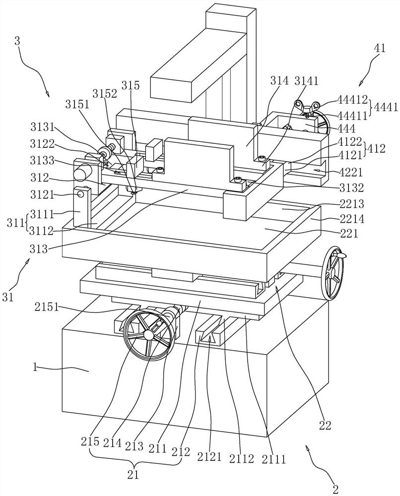
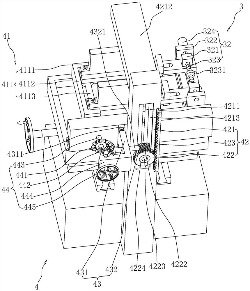
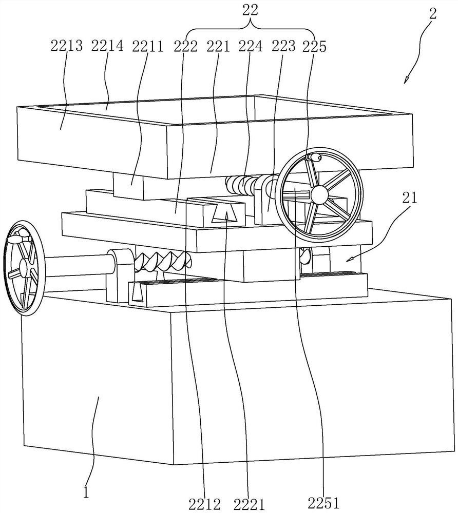
[0039] The following is attached Figure 1-3 The application is described in further detail.

[0040] The embodiment of the application discloses a wire cutting machine. refer to figure 1 and figure 2 , The wire cutting machine includes a workbench 1, a sliding device 2, a clamping device 3, an adjusting device 4 and a cutting device. The shape of the workbench 1 is a cuboid, and the horizontal section of the workbench 1 is a rectangle. The sliding device 2 is installed on the upper surface of the workbench 1, the clamping device 3 is installed on the sliding device 2, the clamping device 3 is used to clamp the workpiece, and the sliding device 2 is used to drive the clamping device 3 to slide in the horizontal direction , the adjusting device 4 is used to adjust the angle of the clamping device 3, and the cutting device is used to cut the workpiece.

[0041] refer to figure 1 and image 3 , the sliding device 2 includes a first sliding mechanism 21 and a second slidin...


PUM


Abstract

The invention relates to the field of cutting equipment, in particular to a wire cutting machine. The wire cutting machine comprises a workbench, a sliding device, a clamping device and an adjusting device, the clamping device comprises a supporting frame and a first bearing block, and the first bearing block is rotationally connected with the supporting frame; the adjusting device comprises a bearing mechanism, a lifting mechanism and a second driving mechanism; the lifting mechanism comprises a supporting plate, a lifting plate, a turbine and a rack; the supporting plate is fixed to the workbench, and a sliding rod is in sliding fit with the supporting plate; the sliding rod penetrates through one end of a sliding groove to be rotationally connected with the turbine, the rack is fixed tothe supporting plate, the turbine is meshed with the rack, and the second driving mechanism is used for driving the turbine to rotate; and the bearing mechanism comprises a bearing frame and a connecting piece, one end of the first bearing block is rotationally connected with the bearing frame, one end of the connecting piece is fixedly connected with the bearing frame, and the other end of the connecting piece is in sliding fit with a fourth dovetail groove. According to the wire cutting machine, workpieces can be prevented from shaking in the workpiece machining process of the wire cuttingmachine.

Description

technical field [0001] The present application relates to the field of cutting equipment, in particular to a wire cutting machine. Background technique [0002] The wire cutting machine is mainly composed of three parts: machine tool, numerical control system and high frequency power supply. The numerical control system is composed of a single-chip microcomputer, a keyboard, and a frequency conversion detection system. It has the main functions of gap compensation, linear interpolation, circular interpolation, and automatic processing of broken wires. It can cut materials, such as high-strength, high-toughness, high-hardness, high-brittleness, magnetic materials, and precision small and complex-shaped parts. Wire cutting technology and wire cutting machine tools are being widely used in all walks of life. [0003] In the related art, the Chinese patent whose authorization notification number is CN208033855U discloses a wire cutting machine, comprising: a machine base; a be...

Claims


Application Information

Patent Timeline
Patent Type & Authority Applications(China)
IPC IPC(8): B23H7/02B23H11/00
CPCB23H7/02B23H11/00
Inventor 孙晓霞李春璟
Owner 景荣精密模具(深圳)有限公司
Why Eureka
Try Eureka