
Methods and systems for generating high peak power laser pulses

A technology of laser pulses and generation methods, applied in lasers, laser devices, laser welding equipment, etc., can solve the problems of complex optical systems, complex and expensive injection, expensive and bulky, etc.

Pending Publication Date: 2021-03-23
IMAGINE OPTIC
View PDF13 Cites 0 Cited by
  • Summary
  • Abstract
  • Description
  • Claims
  • Application Information

AI Technical Summary

Problems solved by technology

However, to limit injection and propagation losses in such components, it is preferable to inject the light energy into each fiber separately, which makes the injection complex and expensive
Furthermore, it is necessary to have an optical focusing system with a large aperture at the output of the component, which makes the optical system complex, expensive and bulky

Method used


Image

  • Methods and systems for generating high peak power laser pulses
  • Methods and systems for generating high peak power laser pulses
  • Methods and systems for generating high peak power laser pulses

Examples


Embodiment Construction

[0064] In this specification, of interest is the generation of high peak power pulses, suitable for generating laser shocks in materials.

[0065] The interaction of high illumination pulses (light power delivered per unit area) (typically on the order of millions of watts per square centimeter) with the material causes sudden heating of the illuminated surface and vaporization of this illuminated surface in the form of a plasma, a plasma And then relax. This is called laser shock. Laser shock is a mechanism in which the light / material interaction time is very short (typically tens of nanoseconds), so that, as with laser cutting or laser welding methods, there is no appreciable increase in the temperature of the part to be processed. Laser shock can be induced in one direction using a constrained layer. Specifically, in the absence of a constrained layer, the spreading of the laser shock occurs in the range of 4π steradians.

[0066] More precisely, in the case of laser sho...


PUM

PropertyMeasurementUnit
diameteraaaaaaaaaa
diameteraaaaaaaaaa

Abstract

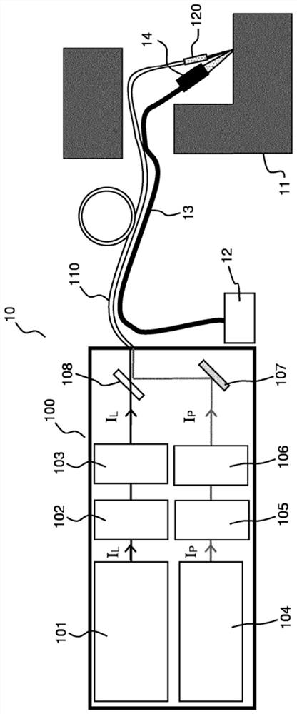
The present description relates to, according to one aspect, a system (10) for generating high peak power laser pulses comprising at least one first light source (101) for emitting first nanosecond laser pulses (IL), a fibre device (110) for carrying said first laser pulses, comprising at least one first multimode fibre with a single core arranged to receive said first laser pulses, and at least one first optical amplifier (120) arranged at the output of said fibre device for the optical amplification of said first laser pulses in order to form said high peak power laser pulses.

Description

technical field [0001] This specification relates to methods and systems for generating high peak power laser pulses for laser shock purposes. This specification applies in particular to laser shock peening, laser shock spectroscopy, laser-based ultrasound generation or laser cleaning of components. Background technique [0002] Laser shock-based surface treatment applications (i.e., involving the formation of plasmas) require pulses with very high peak powers (typically on the order of 10 megawatts (MW) or more), that is, typically require pulses of duration On the order of tens of nanoseconds or less and with energies greater than about one hundred millijoules. These pulses are typically concentrated over an area of ​​a few square millimeters, making it possible to achieve energy densities of tens of joules per square centimeter for forming laser shocks. These applications include, for example, laser shock spectroscopy, laser cleaning, laser-based ultrasound generation (...

Claims


Application Information

Patent Timeline
Patent Type & Authority Applications(China)
IPC IPC(8): H01S3/067H01S3/094H01S3/0941H01S3/23H01S3/00H01S3/06
CPCH01S3/005H01S3/0057H01S3/061H01S3/06754H01S3/094053H01S3/094069H01S3/094076H01S3/09415H01S3/2308H01S2301/03H01S2301/206B23K26/356B23K26/0622C21D10/005H01S5/026H01S5/50
Inventor G·戈尔朱A·爱雅X·列维茨
Owner IMAGINE OPTIC
Learn More