
Electric leakage online monitoring system and method

A technology of electrometry and electro-electronics, applied in the direction of electronic circuit testing, measuring devices, measuring electrical variables, etc., can solve problems such as failure, single purpose, and electric shock accidents of personnel, and achieve low cost, small size, and strong real-time monitoring Effect

Active Publication Date: 2021-03-23
CHINA ELECTRIC POWER RES INST WUHAN BRANCH
View PDF7 Cites 0 Cited by
  • Summary
  • Abstract
  • Description
  • Claims
  • Application Information

AI Technical Summary

Problems solved by technology

[0002] For a long time, the leakage problem has been a big problem to be solved in the field of electrical engineering and electrical equipment. From the power equipment of large substations to street lamps and charging piles, from indoor office appliances to small household appliances, there may be leakage phenomena. The existence of human life safety and the normal use of equipment has brought huge hidden dangers
[0003] Most of the leakage phenomena are caused by unreasonable electrical system or equipment design, damage to the electrical insulation layer or failure of insulation performance, and aging lines. or some intermediate insulating layers, etc.) will form a potential difference with the earth, and when the human body or other objects come into contact with this part, there may be electric shock accidents or short-circuit fire accidents
[0004] The current mainstream anti-leakage solution is to install a leakage protection switch in the circuit. The main principle of the leakage protection switch is to monitor the state of the current in the main circuit to judge whether the leakage phenomenon exists. When the current in the main circuit is abnormal or suddenly rises above a certain threshold When the leakage occurs, it is considered that the leakage phenomenon occurs, and the leakage protection switch acts to cut off the circuit, terminates the leakage, and prevents further occurrence of electric shock or equipment short circuit. When the equipment or line is not reliably grounded, when the leakage occurs, only the potential difference between the insulating part and the earth appears on the insulating part, but there is no abnormal current in the circuit, and the condition for the action of the leakage protection switch is not reached. Correspondingly, the leakage protection When the switch action parts fail, even if the action conditions are met, the main circuit still cannot be disconnected, and the circuit or equipment will be in a leakage state for a long time. Notify the maintenance personnel in time to check the lines or equipment to eliminate hidden dangers
[0005] In power distribution rooms, substations, and places where large-scale electrical equipment is used, electroscopes (electroscopes, electroscopes) are often used to detect whether there is leakage in the lines and equipment, but the electroscopes are usually large in size and have a single purpose. To carry out professional training, at the same time, it is necessary to have a certain understanding of the tested circuit or equipment. Therefore, the commonly used electrometric equipment is only a professional tool for electricians, and cannot be used by ordinary people.

Method used


Image

  • Electric leakage online monitoring system and method
  • Electric leakage online monitoring system and method
  • Electric leakage online monitoring system and method

Examples


Embodiment Construction

[0051] Exemplary embodiments of the present invention will now be described with reference to the drawings; however, the present invention may be embodied in many different forms and are not limited to the embodiments described herein, which are provided for the purpose of exhaustively and completely disclosing the present invention. invention and fully convey the scope of the invention to those skilled in the art. The terms used in the exemplary embodiments shown in the drawings do not limit the present invention. In the figures, the same units / elements are given the same reference numerals.

[0052] Unless otherwise specified, the terms (including scientific and technical terms) used herein have the commonly understood meanings to those skilled in the art. In addition, it can be understood that terms defined by commonly used dictionaries should be understood to have consistent meanings in the context of their related fields, and should not be understood as idealized or over...


PUM


Abstract

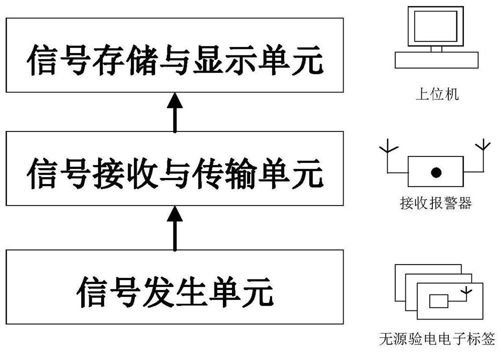
The invention discloses an electric leakage online monitoring system and method, which belong to the technical field of power grid safety and protection. The system comprises a signal acquisition unit, a signal receiving and transmitting unit and a signal storage and display unit, wherein the signal acquisition unit is used for carrying out electricity testing on the surface of a to-be-tested device to obtain an electricity testing result, receiving a query signal transmitted by a signal receiving and transmitting unit, generating a feedback signal according to whether a voltage signal existsin the electricity testing result after receiving the query signal, and feeding back the feedback signal to the signal receiving and transmitting unit; the signal receiving and transmitting unit is used for sending a query signal to the signal acquisition unit at a preset time interval, acquiring a feedback signal of the signal acquisition unit, determining whether electric leakage exists in the to-be-tested device or not according to the feedback signal, completing online monitoring on the to-be-tested device and acquiring an online monitoring result; and the signal storage and display unit is used for receiving the online monitoring result acquired by the signal receiving and transmitting unit and displaying and storing the online monitoring result. The electric leakage condition of theconcerned object can be monitored in real time.

Description

technical field [0001] The invention relates to the technical field of power grid safety and protection, and more specifically, to an online leakage monitoring system and method. Background technique [0002] For a long time, the leakage problem has been a big problem to be solved in the field of electrical engineering and electrical equipment. From the power equipment of large substations to street lamps and charging piles, from indoor office appliances to small household appliances, there may be leakage phenomena. The existence of human life safety and normal use of equipment has brought huge hidden dangers. [0003] Most of the leakage phenomena are caused by unreasonable electrical system or equipment design, damage to the electrical insulation layer or failure of insulation performance, and aging lines. Or some intermediate insulating layers, etc.) will form a potential difference with the earth. When the human body or other objects come into contact with this part, th...

Claims


Application Information

Patent Timeline
Patent Type & Authority Applications(China)
IPC IPC(8): G01R19/00G01R31/28
CPCG01R19/00G01R31/28
Inventor 聂霖袁田郑传广徐莹刘飞邱志鹏朱祥陈柔王昱晴
Owner CHINA ELECTRIC POWER RES INST WUHAN BRANCH
Learn More