
Tool clamp specially for shape correction of blade

A tooling fixture and shape correction technology, which is applied in the direction of manufacturing tools, feeding devices, metal processing, etc., can solve the problem that it is difficult to accurately grasp the angle of blade shape correction, the data judgment basis cannot be provided for the same type of blade shape correction, and the consistency of blades is difficult. Guarantee and other issues, to achieve the effect of shortening the time of shape correction, precise shape correction, and improving the accuracy of shape correction

Active Publication Date: 2021-03-23
SHENYANG LIMING AERO-ENGINE GROUP CORPORATION
View PDF5 Cites 0 Cited by
  • Summary
  • Abstract
  • Description
  • Claims
  • Application Information

AI Technical Summary

Problems solved by technology

[0002] After the current engine blades have been working for a certain period of time, under the influence of various external stresses, the blade body will have different torsional deformations to a certain extent. When the engine is overhauled, the blade shape of the blade needs to be corrected. The traditional Calibration methods such as beating, thermal shaping, etc. are difficult to accurately grasp the angle of blade shaping, and the consistency of blade shaping is also difficult to guarantee; it cannot provide data judgment basis for subsequent blade shaping of the same type

Method used


Image

  • Tool clamp specially for shape correction of blade
  • Tool clamp specially for shape correction of blade
  • Tool clamp specially for shape correction of blade

Examples


Embodiment Construction

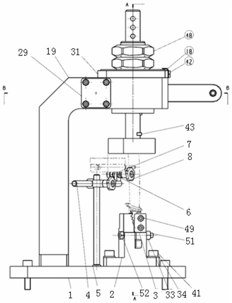
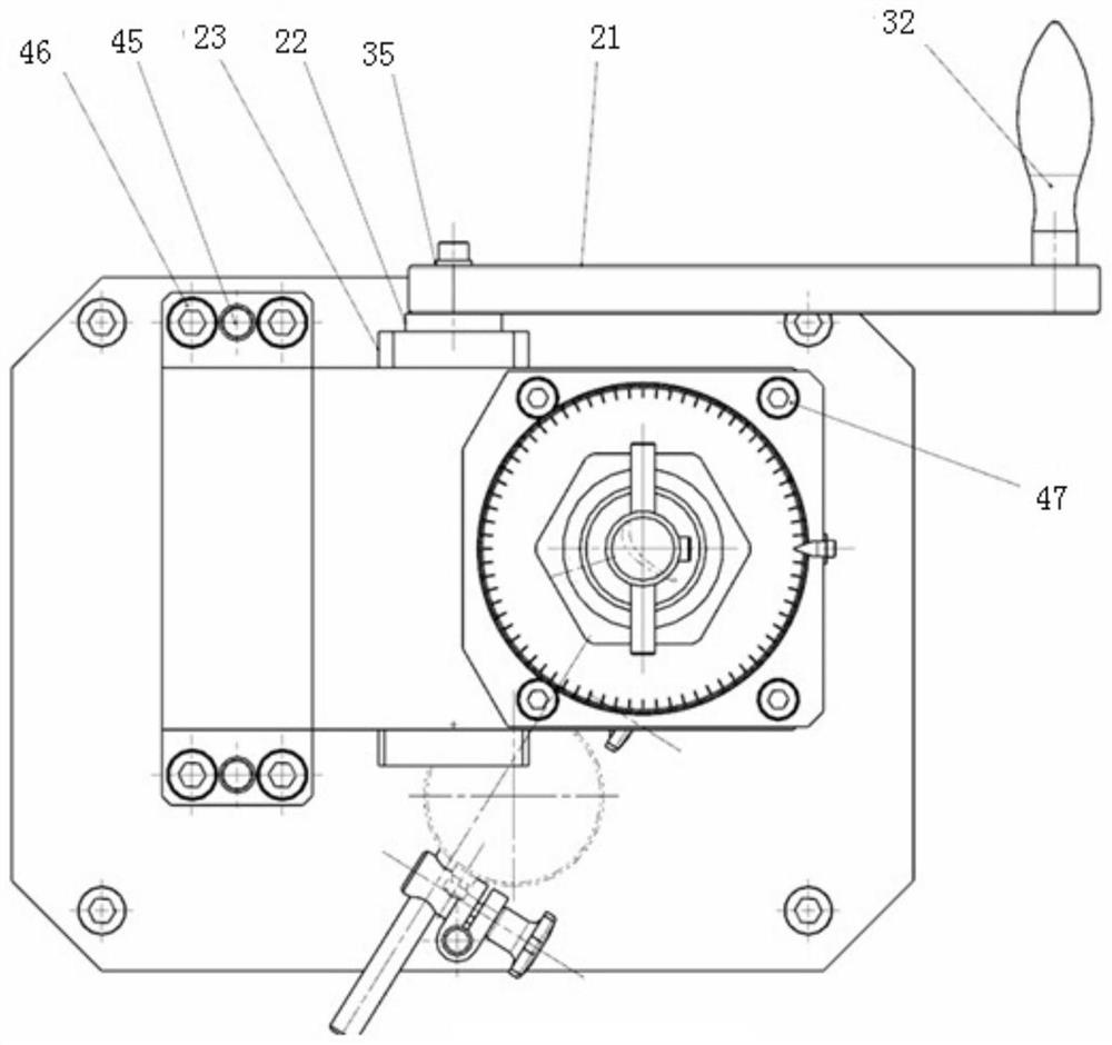
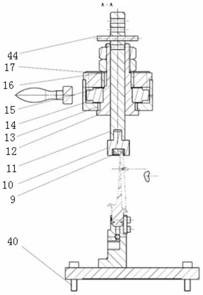
[0042] like Figure 1-4 Shown is a special tooling fixture for blade shape correction, including base plate 1, positioning block 2, baffle plate 3, beam 4, column 5, table clamp 6, screw 7, star nut 9, spacer 9, torque transmission sleeve 10 , Tightening rod 11, rotating shaft 12, bushing a13, turbine 14, adjusting gasket 15, bushing b16, scale gasket 17, pointer 18, positioning seat 19, blocking cover a20, handle 21, washer 22, blocking cover b23, worm 24, felt ring 25, sleeve 28, clip 29, pull rod 30, blocking cover c31;

[0043] The main body of the bottom plate 1 is a cuboid, and the cuboid is provided with mounting holes, and four light holes are provided at the four corners, which are used to fix the overall structure of the fixture on the worktable through hexagon socket head screws a40, and the mounting holes are used for fixing and positioning Block 2, column 5 and positioning seat 19;

[0044] The positioning block 2 is a cuboid, and the positioning block 2 is prov...


PUM


Abstract

The invention discloses a tool clamp specially for shape correction of a blade. The clamp comprises a base plate, a positioning block, a baffle, a cross beam, a torque transmission sleeve, a jacking rod, a turbine, a transmission shaft, a handle and the like. The blade is arranged on the positioning block and connected with the torque transmission sleeve together. During shape correction, the handle is rotated, and the handle and a worm shaft are fixed together through a square groove to move. The worm shaft transmits force to the turbine and drives the torque transmission sleeve to rotate. The torque transmission sleeve and a blade sawtooth crown are located and connected together, a blade body is driven to rotate under the effect of the force, and then the goal of shape correction is achieved. In the operation process, through real-time detection of a detection instrument, it is guaranteed that the blade body is corrected and rotated to a theoretical position. According to the tool clamp, by adopting the characteristics of a worm and gear transmission mechanism and key connection, the technical problem of inaccurate and uncontrollable shape correction in the prior art can be solved.

Description

technical field [0001] The invention relates to the technical field of blade clamps, in particular to a special tooling clamp for blade shape correction. Background technique [0002] After the current engine blades have been working for a certain period of time, under the influence of various external stresses, the blade body will have different torsional deformations to a certain extent. When the engine is overhauled, the blade shape of the blade needs to be corrected. The traditional Calibration methods such as beating, thermal shaping, etc. are difficult to accurately grasp the angle of blade shaping, and the consistency of blade shaping is also difficult to guarantee; it cannot provide data basis for subsequent blade shaping of the same type. Contents of the invention [0003] In order to solve the above technical problems, a special tooling fixture for blade shape correction is proposed. The specific technical scheme is as follows: [0004] A special tooling fixture...

Claims


Application Information

Patent Timeline
IPC IPC(8): B21D53/78B21D3/16B21C51/00B21D43/00
CPCB21D53/78B21D3/16B21C51/00B21D43/003
Inventor 赵海翔阚敏罗敏
Owner SHENYANG LIMING AERO-ENGINE GROUP CORPORATION
Learn More