
Image capturing apparatus, calibration method, and non-transitory computer-readable medium

Active Publication Date: 2015-12-17
FUJIFILM CORP
View PDF25 Cites 7 Cited by
  • Summary
  • Abstract
  • Description
  • Claims
  • Application Information

AI Technical Summary

Benefits of technology

The patent describes an image capturing apparatus that uses guides to improve image quality. The guides can be arranged in different ways to improve calibration and content restoration. The apparatus includes a parameter calculation unit that calculates parameters for the point image restoration process based on the calibration image and the guide. The technical effects of the invention include improved image quality and more precise calibration.

Problems solved by technology

However, PTL 1 does not disclose a technology concerning imaging the chart for adjustment in terms of assistance in imaging.
For this reason, the chart for adjustment may not be properly imaged by the technology described in PTL 1 in some cases.
For this reason, an image may not be properly captured by the technology described in PTL 2 in some cases.
PTL 3 does not disclose a technology concerning acquiring the image data in terms of assistance in imaging.
For this reason, the image data may not be properly acquired by the technology described in PTL 3 in some cases.

Method used


Image

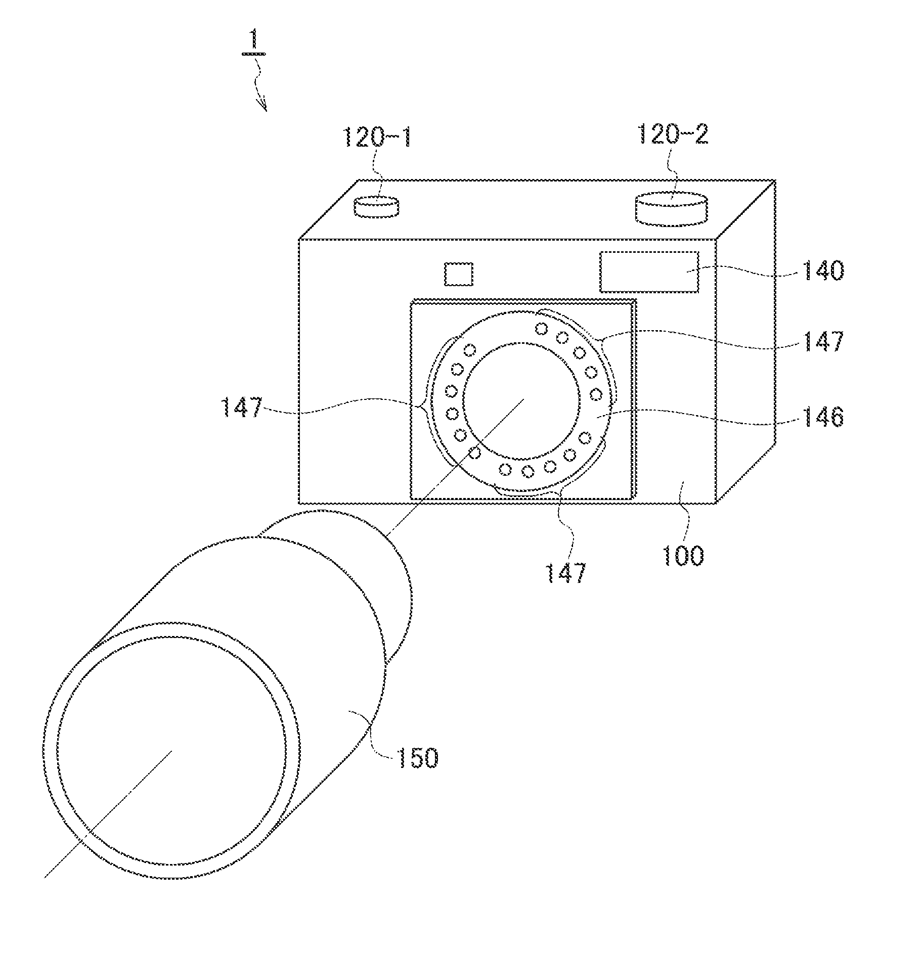
  • Image capturing apparatus, calibration method, and non-transitory computer-readable medium
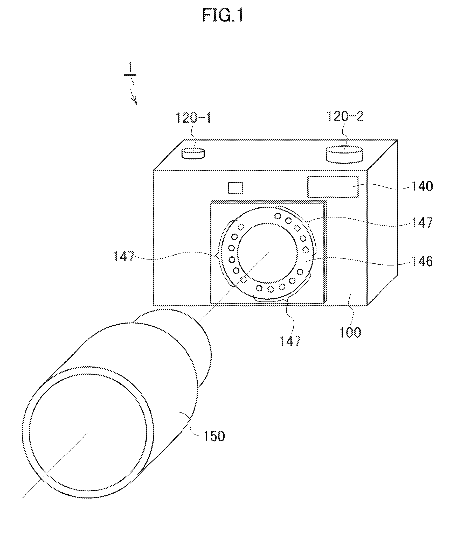
  • Image capturing apparatus, calibration method, and non-transitory computer-readable medium
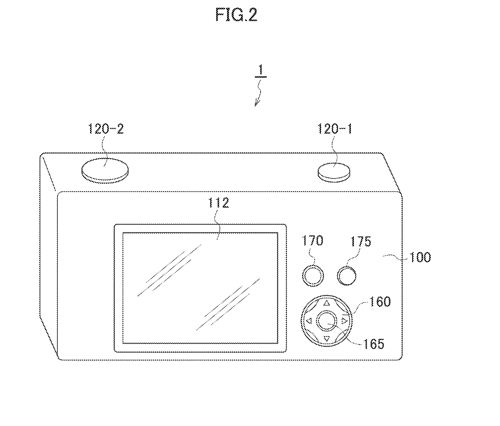
  • Image capturing apparatus, calibration method, and non-transitory computer-readable medium

Examples


modification example 1

[Modification Example 1 of Guide Indication Form]

[0125]FIG. 10A to FIG. 10D each show a modification example 1 concerning the indication form of the guide 10. Elements similar to those in FIG. 6A to FIG. 6D are designated by the same reference numerals and the description thereof is omitted. In comparing the modification example 1 of the guide indication forms shown in FIG. 10A to FIG. 10D with the guide indication pattern shown in FIG. 6D of the guide indication forms shown in FIG. 6A to FIG. 6D, the modification example 1 shown in FIG. 10A to FIG. 10D is different in that the subject satisfying each of guide indications at four corners is imaged at each of guide indications at four corners. Specifically, in the modification example 1 shown in FIG. 10A to FIG. 10D, first, the imaged picture satisfying the guide 10 arranged on the upper left is imaged, as shown in FIG. 10A. Next, the imaged picture satisfying the guide 10 arranged on the upper right is imaged, as shown in FIG. 10B. ...

modification example 2

[Modification Example 2 of Guide Indication Form]

[0128]FIG. 11A to FIG. 11D each show a modification example 2 concerning the indication form of the guide 10. Elements similar to those in FIG. 6A to FIG. 6D are designated by the same reference numerals and the description thereof is omitted. In comparing the modification example 2 of the guide indication forms shown in FIG. 11A to FIG. 11D with the guide indication pattern shown in FIG. 6D of the indication forms of the guide 10 shown in FIG. 6A to FIG. 6D, the modification example 2 shown in FIG. 11A to FIG. 11D is different in that an imaging condition 30 regarding the calibration image is displayed together with the guide 10 on the display screen 112. Specifically, the imaging condition 30 for imaging the calibration image is displayed on the display screen 112 (display unit 225) to notify a person performing the imaging of the necessary imaging condition 30 of the calibration image. Then, the parameter for the point image restor...

modification example 3

[Modification Example 3 of Guide Indication Form]

[0132]With reference to FIG. 12, FIG. 13, FIG. 14, FIG. 15A, and FIG. 15B, a description is given of a modification example 3 of the guide indication form. In the modification example 3 of the guide indication form, further displayed on the display screen 112 is determination information 35 sent by an image analysis determination unit 227 (see FIG. 15A and FIG. 15B).

[0133]In comparing the display unit 225 shown in FIG. 12 with the display unit 225 shown in FIG. 4, the display unit 225 shown in FIG. 12 is different in including an image analysis unit 226 and the image analysis determination unit 227. The image capturing apparatus 1 in the modification example 3 of the guide indication form includes the image analysis unit 226 that analyzes the imaged picture imaged by the image capturing unit 5, and the image analysis determination unit 227 that determines whether or not the imaged picture is adequate as the calibration image on the ba...


PUM


Abstract

An image capturing apparatus according to an aspect of the present invention includes an image capturing unit, a display unit that displays an imaged picture imaged by the image capturing unit and a guide linearly shaped along a sagittal direction or a tangential direction in the imaged picture, the guide assisting imaging of a calibration image used for calibration in a point image restoration process, and a parameter calculation unit that calculates a parameter for the point image restoration process on the basis of the calibration image imaged by the image capturing unit with assistance from the guide.

Description

CROSS-REFERENCE TO RELATED APPLICATIONS[0001]This application is a Continuation of PCT International Application No. PCT / JP2013 / 080412 filed on Nov. 11, 2013, which claims priority under 35 U.S.C. §119(a) to Japanese Patent Application No. 2013-066622 filed on Mar. 27, 2013. Each of the above application(s) is hereby expressly incorporated by reference, in its entirety, into the present application.BACKGROUND OF THE INVENTION[0002]1. Field of the Invention[0003]The present invention relates to a technology concerning an image capturing apparatus, and particularly relates to a point image restoration process performed on an imaged picture on the basis of a point spread function (PSF).[0004]2. Description of the Related Art[0005]Image deterioration caused by various aberrations of an optical system (e.g., imaging lens) sometimes occurs in an imaged picture obtained by imaging a subject by an image capturing apparatus such as a digital camera.[0006]In order to prevent the image deterio...

Claims


Application Information

Patent Timeline
IPC IPC(8): H04N17/00G06T7/00H04N5/232
CPCH04N17/002G06T7/0018H04N5/23222H04N5/23293H04N5/208G06T7/80H04N23/663H04N23/635H04N23/743H04N23/73H04N25/134G06T5/73H04N25/671H04N23/64H04N25/67
Inventor HAYASHI, KENKICHISUGIMOTO, MASAHIKONARUSE, YOUSUKE
Owner FUJIFILM CORP
Learn More