
Rapid calibration method for visual sensor

A visual sensor and calibration method technology, applied in the field of calibration, can solve the problems of low efficiency, complicated operation, and difficulty in ensuring accuracy, and achieve the effects of ensuring accuracy, improving calibration efficiency, and saving calibration time.

Pending Publication Date: 2022-06-03
CHONGQING UNIV
View PDF0 Cites 0 Cited by
  • Summary
  • Abstract
  • Description
  • Claims
  • Application Information

AI Technical Summary

Problems solved by technology

[0003] The existing calibration method has low efficiency, complex operation, and requires a lot of time, and its final accuracy is difficult to be guaranteed

Method used


Image

  • Rapid calibration method for visual sensor
  • Rapid calibration method for visual sensor
  • Rapid calibration method for visual sensor

Examples


Embodiment Construction

[0055] The present invention is further described in detail below:

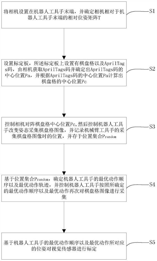
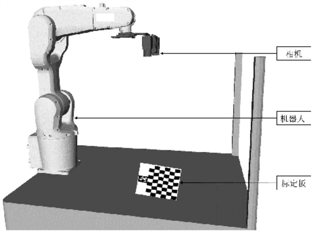
[0056] A visual sensor rapid calibration method provided by the present invention includes the following steps: S1. Set the camera at the end of the robot tool hand, and determine the relative pose matrix T of the camera relative to the end of the robot tool hand;

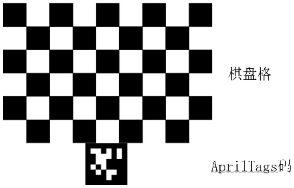
[0057] S2. set up a calibration board, the calibration board is provided with a checkerboard and AprilTags code, the camera obtains the AprilTags code and determines the center position Pa of the AprilTags code, and calculates the center position Pc of the checkerboard according to the center position Pa of the AprilTags code ; Wherein, the central position Pc of the checkerboard is calculated with the central position Pa of the AprilTags code and is realized by the existing geometric algorithm;

[0058] S3. Control the camera to face the checkerboard center position Pc, and then control the robot tool hand to change the posture to collect the che...


PUM


Abstract

The invention provides a quick calibration method for a visual sensor, which comprises the following steps of: arranging a camera at the tail end of a robot tool hand, and determining a relative pose matrix of the camera relative to the tail end of the robot tool hand; the method comprises the steps that a calibration board is arranged, a checkerboard and an AprilTags code are arranged on the calibration board, the AprilTags code is acquired by a camera, the center position of the AprilTags code is determined, and the center position of the checkerboard is calculated according to the center position of the AprilTags code; the camera is controlled to align to the center position Pc of the checkerboard, then the robot tool hand is controlled to change the posture to collect checkerboard images, and the position of the mechanical arm tool hand when the checkerboard images are collected is recorded and stored in a position set; based on the position set, determining an optimal action sequence and an optimal action track of the robot tool hand, and controlling the robot tool hand to collect the checkerboard image again according to the determined optimal action sequence and optimal action; and calibrating the visual sensor based on the optimal action sequence of the robot tool hand and the pose corresponding to the optimal action.

Description

technical field [0001] The invention relates to a calibration method, in particular to a rapid calibration method of a visual sensor. Background technique [0002] The intelligent development of robots is to make robots have the ability to perceive the external environment and coordinate with the operator. Robot vision is to use the principle of machine vision to quickly and accurately obtain external environment information from image information, and feed it back to the robot control system to make quick responses. Machine vision is applied to industrial robots, so that the robot can adjust the robot operation according to the changes of external information fed back by image processing, thus greatly improving the environmental adaptability and flexibility of the robot. For a robotic system with vision, all the information obtained by the camera is described in the camera coordinate system. In order to establish a relationship between the coordinate system of the camera ...

Claims


Application Information

Patent Timeline
IPC IPC(8): B25J9/16G06T7/70G06T7/80H04N5/225
CPCB25J9/1653B25J9/1661B25J9/1692G06T7/80G06T7/70H04N23/57
Inventor 唐倩张志豪郭伏雨陈佳伟
Owner CHONGQING UNIV
Learn More