Die

A mold and punch technology, applied in the field of machining, can solve the problems of easy wear of the blank holder, easy jamming of the drawbead and blank holder, and achieve the effects of increasing resistance, sufficient plastic deformation, and not easy to wear.

Pending Publication Date: 2021-03-23
SAIC-GM-WULING AUTOMOBILE CO LTD
View PDF5 Cites 0 Cited by
  • Summary
  • Abstract
  • Description
  • Claims
  • Application Information

AI Technical Summary

Problems solved by technology

[0005] The technical solution of the present application provides a mold to solve the technical problems in the prior art that the material is easily jammed between the drawbead and the blank holder and the blank holder is easy to wear

Method used


Image

  • Die
  • Die
  • Die

Examples


Embodiment Construction

[0042] The terms used in the embodiments of the present application are only used to explain specific embodiments of the present application, and are not intended to limit the present application.

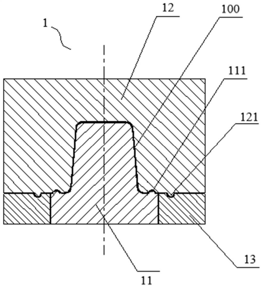
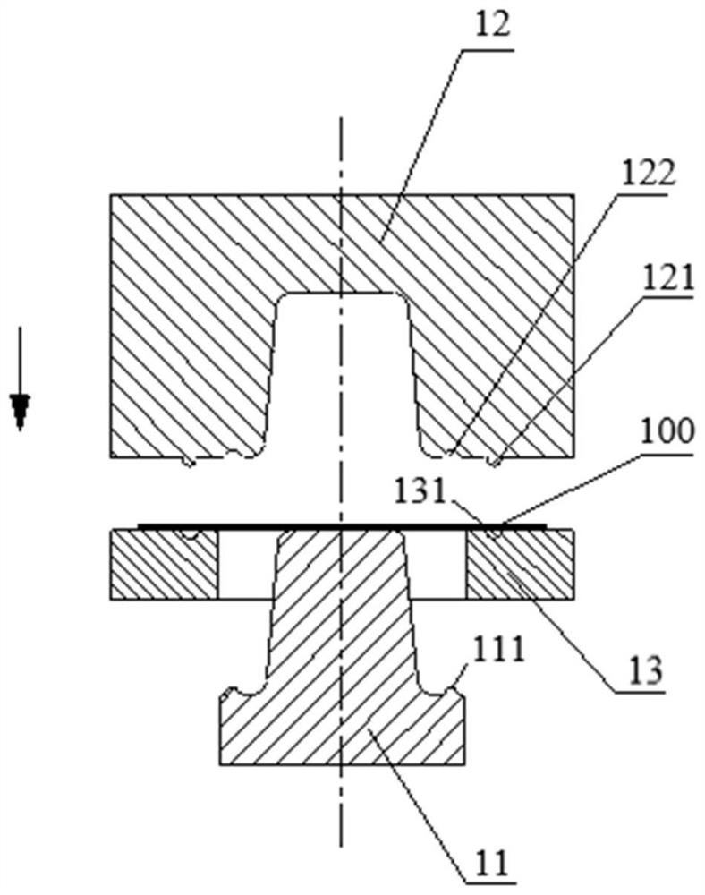
[0043] figure 2 It is a partial structural sectional view of a mold in the embodiment of the present application, such as figure 2 As shown, the embodiment of the present application provides a mold 1, including a punch 11, a die 12 and a blank holder 13, wherein the blank holder 13 is sleeved on the punch 11 to support the workpiece together with the punch 11 100. The concave mold 12 is used for concave-convex cooperation with the convex mold 11 to stamp the workpiece 100 .

[0044] refer to image 3 , in the above-mentioned mold 1, among the blank holder 13 and the die 12, one is provided with a first groove 131, and the other is fixedly provided with a first drawbead 121, and the first drawbead 121 and the first recess The groove 131 cooperates with the workpiece 100 .

...


PUM


Abstract

The invention provides a die. The die comprises a male die, a female die and a blank holder, wherein the blank holder is arranged on the male die in a sleeving manner and used for supporting a workpiece together with the male die; the female die is used for being matched with the male die in a concave-convex manner to stamp the workpiece; first grooves are formed in one of the blank holder and thefemale die, and first drawing ribs are fixedly arranged on the other one of the blank holder and the female die; the first drawing ribs and the first grooves are matched to act on the workpiece; a second groove is formed in one of the male die and the female die, and a second drawing rib is fixedly arranged on the other one of the male die and the female die; and the second drawing rib and the second groove are matched to act on the workpiece. According to the die, the first drawing ribs and the second drawing rib are both fixedly arranged, so that the phenomenon of material blockage betweenthe drawing ribs and the blank holder is avoided, and the blank holder is not easy to wear.

Description

technical field [0001] The present application relates to the technical field of mechanical processing, in particular to a mold. Background technique [0002] Stamping parts, especially U-shaped parts, are widely used in auto parts. However, due to its complex structure and shape, it is difficult to make all parts of the material enter the yield flow during the forming process. Due to insufficient plastic deformation, problems such as springback and warping are often prone to occur, resulting in reduced precision of parts, which brings great harm to the matching of the whole vehicle. Negative Effects. In recent years, in order to meet fuel economy requirements, the trend of lightweight auto parts has become increasingly obvious. Various high-strength and ultra-high-strength steels are widely used in U-shaped parts such as automotive longitudinal beams. Due to the improvement of material strength, it is easier to Defects such as springback and warpage occur. [0003] refer...

Claims


Application Information

Patent Timeline
Patent Type & Authority Applications(China)
IPC IPC(8): B21D37/10
CPCB21D37/10
Inventor 周江奇沈云啸韦韡李恒佰张峰李开文
Owner SAIC-GM-WULING AUTOMOBILE CO LTD
Why Eureka
Try Eureka