


Quick Research
Generate reliable direction feasibility study reports for your R&D in just a few steps.

Technical Q&A
Discover and master advanced knowledge NOW. Basics, ideas, possibilities, all at once.

Find Solutions
As an expert in R&D theories, this can generate solutions to your technical problems instantly.

Evaluate Feasibility
Analyze your overall solution with one click, know your potential R&D risks in advance.

Monitor Landscape
Get weekly tech updates, stay abreast of the latest tech innovations and key insights.
Method for extracting vanadium by bottom blowing of CO2 at converter
A converter bottom blowing and CO2 technology, which is applied in the field of vanadium metallurgy, can solve the problems of incomplete melting, fast rhythm, block coolant can not continuously control the temperature of the molten pool, etc., and achieve the goal of reducing the content of residual vanadium and suppressing the temperature rise of the molten pool Effect
- Summary
- Abstract
- Description
- Claims
- Application Information
AI Technical Summary
Problems solved by technology
Method used
Image

Examples
Embodiment 1
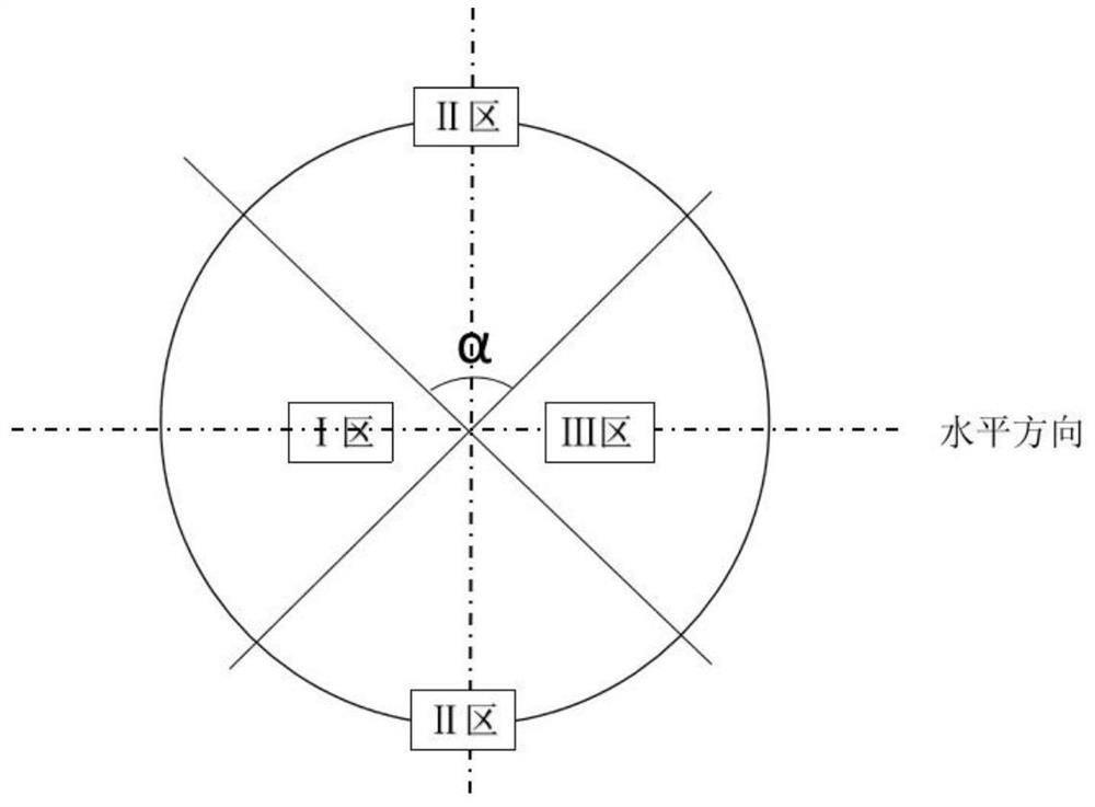
[0027] Mix molten iron with a V content of 0.28-0.34% into the converter, control the temperature of the molten iron at 1260-1320 °C, and distribute the breathable bricks in the zone I, zone II and zone III of the bottom of the converter. The number of breathable bricks matches the furnace capacity, and zone I 1. The air-permeable bricks in zone III are symmetrically distributed, and the air-permeable bricks in zone II are symmetrically distributed, and the included angle α in zone II is 80°. Blowing CO at the bottom of the converter 2 , blowing CO at the bottom of a single ventilating brick in Zone I 2 The flow rate is 170Nm 3 / min, blowing CO at the bottom of a single ventilating brick in Zone II 2 The flow rate is 100Nm 3 / min, blowing CO at the bottom of a single ventilating brick in Zone III 2 Flow 170Nm 3 / min, after 4 minutes of blowing, use an oxygen lance to blow O 2 +CO 2 Mixed gas, CO 2 The volume content is 12%, and the oxygen supply intensity is 1.5-3.0Nm ...
Embodiment 2
[0029] Mix molten iron with a V content of 0.28-0.34% into the converter, control the temperature of the molten iron at 1260-1320 °C, and distribute the breathable bricks in the zone I, zone II and zone III of the bottom of the converter. The number of breathable bricks matches the furnace capacity, and zone I 1. The air-permeable bricks in zone III are symmetrically distributed, and the air-permeable bricks in zone II are symmetrically distributed, and the included angle α in zone II is 100°. Blowing CO at the bottom of the converter2 , blowing CO at the bottom of a single ventilating brick in Zone I 2 The flow rate is 200Nm 3 / min, blowing CO at the bottom of a single ventilating brick in Zone II 2 The flow rate is 130Nm 3 / min, blowing CO at the bottom of a single ventilating brick in Zone III 2 Flow 200Nm 3 / min, after 4 minutes of blowing, use an oxygen lance to blow O 2 +CO 2 Mixed gas, CO 2 The volume content is 25%, and the oxygen supply intensity is 1.5-3.0Nm ...
PUM
 Abstract
Description
Claims
Application Information
 - R&D Engineer
- R&D Manager
- IP Professional
- Industry Leading Data Capabilities
- Powerful AI technology
- Patent DNA Extraction
Browse by: Latest US Patents, China's latest patents, Technical Efficacy Thesaurus, Application Domain, Technology Topic, Popular Technical Reports.
© 2024 PatSnap. All rights reserved.Legal|Privacy policy|Modern Slavery Act Transparency Statement|Sitemap|About US| Contact US: help@patsnap.com