
Environment-friendly building perforating device with positioning structure

A positioning structure and punching device technology, applied in positioning devices, feeding devices, manufacturing tools, etc., can solve the problems of reduced safety of devices, inconvenient use of building panels, and deviation of formed holes, so as to reduce workload and prevent splashing Effect

Pending Publication Date: 2021-03-19
山东港基建设集团有限公司
View PDF0 Cites 0 Cited by
  • Summary
  • Abstract
  • Description
  • Claims
  • Application Information

AI Technical Summary

Problems solved by technology

[0007] The purpose of the present invention is to provide a punching device for environmentally friendly buildings with a positioning structure, so as to solve the problem that some existing punching devices for environmentally friendly buildings on the market proposed by the above-mentioned background technology only rely on building boards to punch holes. The gravity of the board itself is used to fix the board. Since the punching will generate vibration, and there is a certain danger in fixing the building board manually or by the staff, it is easy to make the formed hole deviate when the building board is punched. Then it is not convenient for the subsequent use of building boards, and when some existing environmental protection building drilling devices are used for punching building boards, although through the transmission action, the waste chips generated by the suction fan punching the entire device Due to the limited suction of the suction fan, it is difficult to ensure that the drilling head will collect the splashed waste when drilling, which reduces the safety of the entire device and increases the workload of the staff for secondary cleaning The problem

Method used


Image

  • Environment-friendly building perforating device with positioning structure
  • Environment-friendly building perforating device with positioning structure
  • Environment-friendly building perforating device with positioning structure

Examples


Embodiment Construction

[0027] The following will clearly and completely describe the technical solutions in the embodiments of the present invention with reference to the accompanying drawings in the embodiments of the present invention. Obviously, the described embodiments are only some, not all, embodiments of the present invention. Based on the embodiments of the present invention, all other embodiments obtained by persons of ordinary skill in the art without making creative efforts belong to the protection scope of the present invention.

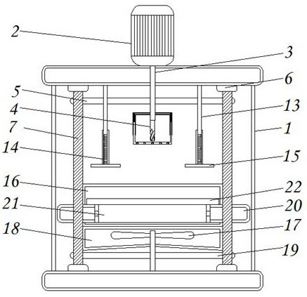
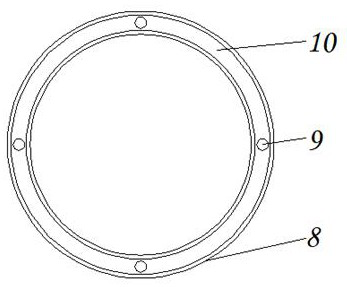
[0028] see Figure 1-7 , the present invention provides a technical solution: a drilling device for environmentally friendly buildings with a positioning structure, including a processing table 1, a servo motor 2, a drive shaft 3, a drilling head 4, a first transmission belt 5, a bearing block 6, a rotating Rod 7, protective frame 8, first return spring 9, shielding frame 10, accommodating groove 11, accelerating ball 12, connecting rod 13, second return sprin...


PUM


Abstract

The invention discloses an environment-friendly building perforating device with a positioning structure. The device comprises a machining table, a servo motor, a protection frame, a shielding frame,a compaction plate and a containing table. The servo motor is fixed to the upper surface of the machining table through bolts, a driving shaft is fixedly welded to the output end of the servo motor, and the lower surface of the driving shaft is in threaded connection with a drilling head. A containing groove is formed in the lower surface of the shielding frame, acceleration balls are arranged inthe containing groove, connecting rods are fixedly welded to the top of the inner side of the machining table, second reset springs are fixedly welded to the lower ends of the connecting rods, the compaction plate is arranged on the outer surfaces of the connecting rods, a feeding port is formed in the surface of the rear side of the machining table, and the lower surface of the inner side of themachining table is rotationally connected with an air suction fan. According to the environment-friendly building perforating device with the positioning structure, the protection frame, first reset springs, the shielding frame and the containing groove are arranged, splashing of scraps can be reduced, and therefore the workload of secondary cleaning of workers is reduced.

Description

technical field [0001] The invention relates to the technical field of environment-friendly buildings, in particular to a punching device for environment-friendly buildings with a positioning structure. Background technique [0002] The earth is the environment we live in. In order to make our children and grandchildren have a good living environment, we need to protect the living environment, and with the improvement of people's awareness of environmental protection, in all walks of life, we have made some actions against non-environmental protection behaviors. For example, in the construction industry, in the construction industry, the traditional boards have been replaced by environmentally friendly boards, making the building an environmentally friendly building, which not only lowers the construction cost, but also improves the work efficiency of the staff. The use of environmentally friendly boards Before that, it is necessary to punch holes on the board, and then it i...

Claims


Application Information

Patent Timeline
IPC IPC(8): B23B41/00B23B47/20B23Q3/06B23Q11/00B08B5/04
CPCB23B41/00B23Q5/28B23Q3/064B23Q11/0046B08B5/04
Inventor 卢鹏里罗宏训李兴满王琳琳冯伟
Owner 山东港基建设集团有限公司
Learn More