
Pass-over roller assembly, coating equipment and rolling equipment

A technology of passing rolls and components, which is applied in the direction of metal processing equipment, electrical components, structural parts, etc., can solve the problems of reduced production capacity, wrinkling, and inability to ensure that the tension of wide-width foils is completely consistent, so as to improve manufacturing capacity and reduce waste Effect

Pending Publication Date: 2021-03-19
SUNWODA ELECTRIC VEHICLE BATTERY CO LTD
View PDF0 Cites 5 Cited by
  • Summary
  • Abstract
  • Description
  • Claims
  • Application Information

AI Technical Summary

Problems solved by technology

However, limited by the existing foil manufacturing technology, the tension of the wide foil in the transverse direction cannot be guaranteed to be completely consistent, and the existing coating and rolling equipment cannot provide the transverse stretching tension to the foil to overcome the incoming material. Differences in tension, causing wrinkling anomalies to occur
In addition, there is a certain difference in the lateral weight of the active material loaded on the foil after coating, which will also cause the foil to be easily wrinkled due to uneven lateral tension during coating, resulting in a decrease in production capacity and even scrapping
In addition, the thickness of the active slurry on the surface of the foil after coating is difficult to achieve uniformity in the transverse direction. During the subsequent rolling, the area with a thicker active slurry on the foil will be squeezed and stretched more, while the foil The area with a smaller thickness of the active paste on the foil is extruded and stretched less, so that the coated foil is also prone to wrinkling in the transverse direction when it is rolled

Method used


Image

  • Pass-over roller assembly, coating equipment and rolling equipment
  • Pass-over roller assembly, coating equipment and rolling equipment
  • Pass-over roller assembly, coating equipment and rolling equipment

Examples


Embodiment Construction

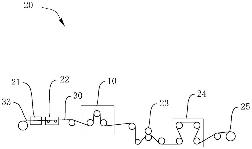
[0027] In order to make the above-mentioned purpose, features and advantages of the present application more obvious and understandable, the specific implementation manners of the present application will be described in detail below in conjunction with the accompanying drawings. In the following description, numerous specific details are set forth in order to provide a thorough understanding of the application. However, the present application can be implemented in many other ways different from those described here, and those skilled in the art can make similar improvements without departing from the connotation of the present application, so the present application is not limited by the specific embodiments disclosed below.

[0028] In the description of the present application, it should be understood that the terms "center", "longitudinal", "transverse", "length", "width", "thickness", "upper", "lower", "front", " Back", "Left", "Right", "Vertical", "Horizontal", "Top", "...


PUM

PropertyMeasurementUnit
thicknessaaaaaaaaaa

Abstract

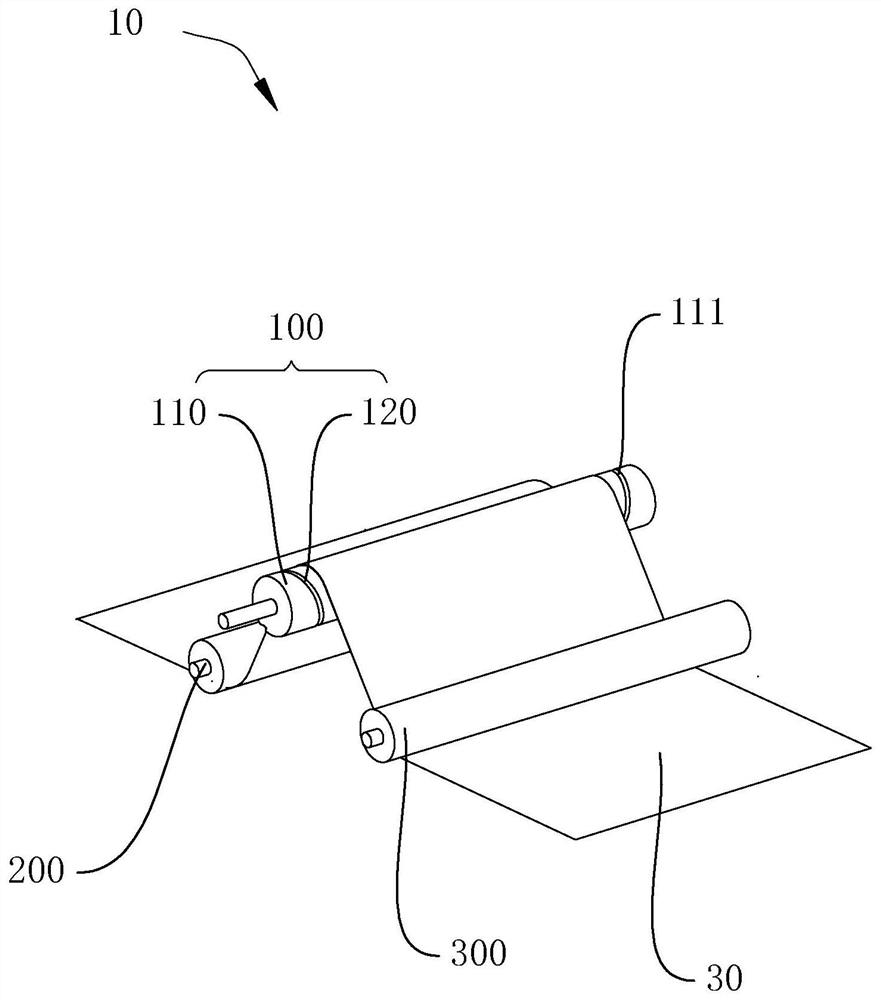
The invention relates to a pass-over roller assembly, coating equipment and rolling equipment. The pass-over roller assembly comprises a threaded roller, a first adjusting roller and a second adjusting roller, wherein the threaded roller comprises an alloy roller and fillers; the surface of the alloy roller is provided with threaded grooves; the threaded grooves are symmetrically and continuouslydistributed in the direction from the center of the alloy roller to the two ends of the alloy roller; the fillers are embedded in the threaded grooves; the surfaces of the fillers are flush with the surface of the alloy roller; the friction coefficients of the surfaces of the fillers are larger than the friction coefficient of the surface of the alloy roller; and the first adjusting roller and thesecond adjusting roller are located on the two opposite sides of the threaded roller respectively and used for adjusting the wrap angle alpha between the threaded roller and a sheet-shaped roller passing object. According to the pass-over roller assembly, the coating equipment and the rolling equipment provided by the invention, when the sheet-shaped roller passing object is arranged on the threaded roller in a penetrating and wrapping mode, the threaded roller can apply continuous and stable transverse tension to the sheet-shaped roller passing object, the transverse tension extends from thecenter of the threaded roller to the two ends, and then transverse wrinkles in the width direction of the sheet-shaped roller passing object can be flattened.

Description

technical field [0001] The present application relates to the technical field of rollers, in particular to a roller assembly, coating equipment and rolling equipment. Background technique [0002] Processes such as coating and rolling are important links in the current lithium-ion battery pole piece forming production process. On the road of developing new batteries and improving the production capacity of coating and rolling, wide foil coating and wide rolling technology will become the key research technology of lithium ion battery manufacturing industry. However, limited by the existing foil manufacturing technology, the tension of the wide foil in the transverse direction cannot be guaranteed to be completely consistent, and the existing coating and rolling equipment cannot provide the transverse stretching tension to the foil to overcome the incoming material. Tension differences, resulting in wrinkling abnormalities. In addition, there is a certain difference in the ...

Claims


Application Information

Patent Timeline
Patent Type & Authority Applications(China)
IPC IPC(8): B21B1/22B21B15/00B21B38/04H01M4/139
CPCB21B1/22B21B15/00B21B38/04H01M4/139B21B2001/221B21B2015/0057Y02E60/10B21D1/02
Inventor 蒋翌梁杰铬唐子颖吴强
Owner SUNWODA ELECTRIC VEHICLE BATTERY CO LTD
Learn More