


Quick Research
Generate reliable direction feasibility study reports for your R&D in just a few steps.

Technical Q&A
Discover and master advanced knowledge NOW. Basics, ideas, possibilities, all at once.

Find Solutions
As an expert in R&D theories, this can generate solutions to your technical problems instantly.

Evaluate Feasibility
Analyze your overall solution with one click, know your potential R&D risks in advance.

Monitor Landscape
Get weekly tech updates, stay abreast of the latest tech innovations and key insights.
Instrument rack for operating forceps production
A technology for instrument racks and surgical forceps, which is applied in the field of instrument racks for the production of surgical forceps. It can solve the problems of placing surgical forceps without classification functions, poor aesthetics of instrument racks, and low stability of instrument racks, so as to meet the needs of modern processing and production. Avoid confusion and facilitate orderly placement
- Summary
- Abstract
- Description
- Claims
- Application Information
AI Technical Summary
Problems solved by technology
Method used
Image

Examples
Embodiment 1
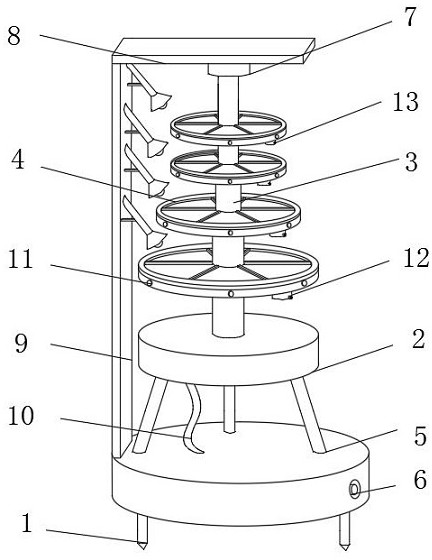
[0031] A kind of instrument holder for the production of surgical forceps, such as figure 1 As shown, the base 5 is included, the upper end of the base 5 is fixedly installed with a chassis 2, and a No. 1 connecting wire 10 is fixedly connected between the chassis 2 and the base 5, and a driving device 3 is fixedly installed inside the chassis 2, and the upper end of the driving device 3 runs through the middle of the upper end of the chassis 2 The upper part of the driving device 3 is fixedly sleeved with a number of tray parts 4 distributed at equal intervals, and the size of the plurality of tray parts 4 increases sequentially from top to bottom. A disinfection device 9 is fixedly installed on the left side of the base 5. The upper end of the disinfection device 9 is fixedly installed with a Top plate 8, No. 1 bearing seat 7 is fixedly installed on the lower end of top plate 8, the lower end of No. 1 bearing seat 7 is movably connected with the upper end of drive device 3, a...
Embodiment 2
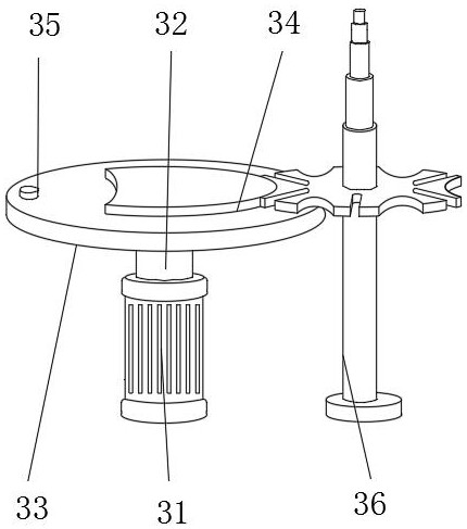
[0034] On the basis of Example 1, as Figure 2-5 As shown, an instrument rack used for the production of surgical forceps includes a base 5, the upper end of the base 5 is fixedly installed with a chassis 2, a connecting wire 10 is fixedly connected between the chassis 2 and the base 5, and a driving device is fixedly installed inside the chassis 2 3. The upper end of the driving device 3 runs through the middle of the upper end of the chassis 2. The upper part of the driving device 3 is fixedly sleeved with a number of tray parts 4 distributed at equal intervals, and the size of the several tray parts 4 increases sequentially from top to bottom. The left side of the base 5 is fixedly installed with Disinfection device 9, the top plate 8 is fixedly installed on the upper end of the disinfection device 9, the No. 1 bearing seat 7 is fixedly installed on the lower end of the top plate 8, the lower end of the No. 1 bearing seat 7 is movably connected with the upper end of the driv...
Embodiment 3
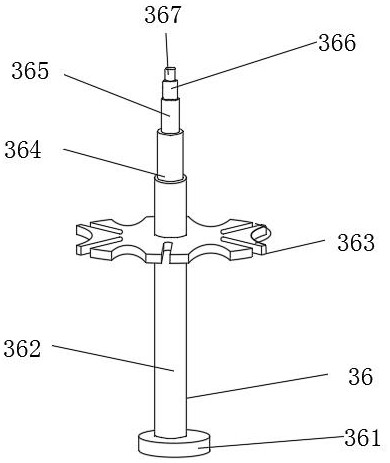
[0037] On the basis of Example 1, as Figure 5-7 As shown, an instrument rack used for the production of surgical forceps includes a base 5, the upper end of the base 5 is fixedly installed with a chassis 2, a connecting wire 10 is fixedly connected between the chassis 2 and the base 5, and a driving device is fixedly installed inside the chassis 2 3. The upper end of the driving device 3 runs through the middle of the upper end of the chassis 2. The upper part of the driving device 3 is fixedly sleeved with a number of tray parts 4 distributed at equal intervals, and the size of the several tray parts 4 increases sequentially from top to bottom. The left side of the base 5 is fixedly installed with Disinfection device 9, the top plate 8 is fixedly installed on the upper end of the disinfection device 9, the No. 1 bearing seat 7 is fixedly installed on the lower end of the top plate 8, the lower end of the No. 1 bearing seat 7 is movably connected with the upper end of the driv...
PUM
 Abstract
Description
Claims
Application Information
 - R&D Engineer
- R&D Manager
- IP Professional
- Industry Leading Data Capabilities
- Powerful AI technology
- Patent DNA Extraction
Browse by: Latest US Patents, China's latest patents, Technical Efficacy Thesaurus, Application Domain, Technology Topic, Popular Technical Reports.
© 2024 PatSnap. All rights reserved.Legal|Privacy policy|Modern Slavery Act Transparency Statement|Sitemap|About US| Contact US: help@patsnap.com