Charging station locating and sizing method and device and storage medium

A technology for site selection, capacity determination, and charging stations, which is applied in the direction of instruments, data processing applications, and forecasting. It can solve problems such as inaccurate load forecasting simulation results, inconsistent driving rules, and inability to accurately determine the installation location and capacity of charging stations.

Pending Publication Date: 2021-03-12
ELECTRIC POWER RESEARCH INSTITUTE, CHINA SOUTHERN POWER GRID CO LTD +1
View PDF2 Cites 2 Cited by
  • Summary
  • Abstract
  • Description
  • Claims
  • Application Information

AI Technical Summary

Problems solved by technology

The existing electric vehicle charging load simulation model inputs the set traffic data as external data into the model when simulating the driving of electric vehicles, but ignores the time-space transfer of vehicles. In actual situations, the traffic conditions themselves will also be affected by the model. The influence of all vehicle driving states, the traffic road network model and the time-space transfer model of traffic flow are two-way interaction, the existing electric vehicle charging load simulation model does not consider the change of traffic road conditions with the time-space transfer of vehicles, resulting in vehicle The driving law of the vehicle does not match the actual vehicle driving law, and the load forecasting simulation results are not accurate, so that the installation location and capacity of the charging station cannot be accurately determined to meet the charging needs of electric vehicles.

Method used


Image

  • Charging station locating and sizing method and device and storage medium
  • Charging station locating and sizing method and device and storage medium
  • Charging station locating and sizing method and device and storage medium

Examples


Embodiment Construction

[0075] The following will clearly and completely describe the technical solutions in the embodiments of the present invention with reference to the accompanying drawings in the embodiments of the present invention. Obviously, the described embodiments are only some, not all, embodiments of the present invention. Based on the embodiments of the present invention, all other embodiments obtained by persons of ordinary skill in the art without creative efforts fall within the protection scope of the present invention.

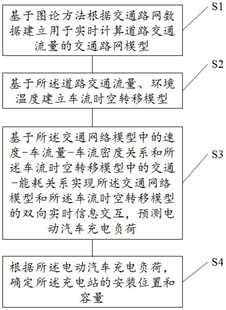
[0076] see figure 1 , which is a schematic flowchart of a method for selecting a location and capacity of a charging station provided by an embodiment of the present invention. The method for selecting a location and capacity of a charging station includes:

[0077] S1. Establishing a traffic network model for real-time calculation of road traffic flow based on the graph theory method according to the traffic road network data; wherein, the traffic road network dat...


PUM


Abstract

The invention discloses a charging station locating and sizing method and device. The method comprises the following steps: establishing a traffic network model for calculating road traffic flow in real time according to traffic network data based on a graph theory method, wherein the traffic network data comprises at least two road nodes, longitude and latitude coordinates of the road nodes, a road node connection relationship and the number of electric vehicles among the road nodes with the connection relationship; establishing a traffic flow space-time transfer model based on the road traffic flow and the environment temperature; and achieving information interaction between the traffic network model and the traffic flow space-time transfer model based on the speed, traffic flow and traffic flow density relationship in the traffic network model and the traffic energy consumption relationship in the traffic flow space-time transfer model, predicting the charging load, and determiningthe installation position and capacity of the charging station according to the charging load. The charging load simulation result is closer to the actual load, the installation position and the required capacity of the charging station are accurately determined according to the charging load, and power supply balance is achieved.

Description

technical field [0001] The invention relates to the field of power system planning and operation, in particular to a method, device and storage medium for site selection and capacity determination of charging stations. Background technique [0002] With the increasingly prominent problems of global warming and air pollution, the scale of electric vehicles and the demand for charging have ushered in a new round of growth. The large-scale charging load access will have a greater impact on the safe and stable operation of the power grid. Forecasting is performed to site and capacity charging stations based on the predicted charging load. The existing electric vehicle charging load simulation model inputs the set traffic data as external data into the model when simulating the driving of electric vehicles, but ignores the time-space transfer of vehicles. In actual situations, the traffic conditions themselves will also be affected by the model. The influence of all vehicle driv...

Claims


Application Information

Patent Timeline
IPC IPC(8): G06Q10/04G06Q10/06G06Q50/06
CPCG06Q10/043G06Q10/067G06Q50/06
Inventor 宋雨浓毛田吴宛潞郭小璇程兰芬肖静周平冯玉斌
Owner ELECTRIC POWER RESEARCH INSTITUTE, CHINA SOUTHERN POWER GRID CO LTD
Why Eureka
Try Eureka