Spherical milling cutter for machining stepped hole chamfer and machining method for machining stepped hole chamfer

The technology of a spherical milling cutter and a processing method, which is applied in the field of automobile parts processing, can solve the problems of high labor intensity, and achieve the effect of reducing labor intensity and improving production efficiency.

Active Publication Date: 2021-03-12
HONDA FOUNDRY (FOSHAN) CO LTD
View PDF9 Cites 0 Cited by
  • Summary
  • Abstract
  • Description
  • Claims
  • Application Information

AI Technical Summary

Problems solved by technology

[0005] In view of the deficiencies in the prior art above, the purpose of the present invention is to provide a spherical milling cutter for processing step hole chamfering and a processing method for processing step hole chamfering, so as to solve the problem that the chamfering of existing processing step holes needs manual Labor-intensive problems caused by manual grinding

Method used


Image

  • Spherical milling cutter for machining stepped hole chamfer and machining method for machining stepped hole chamfer
  • Spherical milling cutter for machining stepped hole chamfer and machining method for machining stepped hole chamfer
  • Spherical milling cutter for machining stepped hole chamfer and machining method for machining stepped hole chamfer

Examples


Embodiment Construction

[0038] The present invention provides a spherical milling cutter for processing stepped hole chamfering and a processing method for processing stepped hole chamfering. Detailed description. It should be understood that the specific embodiments described here are only used to explain the present invention, and are not intended to limit the protection scope of the present invention.

[0039] refer to Figure 1-4 , a processing method for processing step hole chamfering, comprising the following steps:

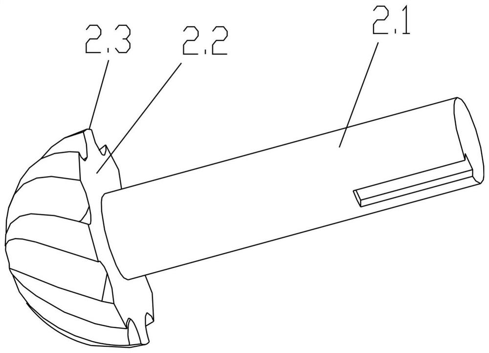
[0040] a. Select spherical milling cutter 2. Among them, the selected spherical milling cutter 2 includes a handle 2.1 and a spherical cutter head 2.2, the spherical cutter head 2.2 is less than or equal to half a sphere, and a blade 2.3 is provided on the outer surface of the spherical cutter head 2.2, and the diameter of the handle 2.1 is smaller than the largest The outer diameter of the widest part of the blade 2.3, and the axis of the handle 2.1 is perpendicular to the en...


PUM


Abstract

The invention discloses a spherical milling cutter for machining a stepped hole chamfer and a machining method for machining the stepped hole chamfer. According to the spherical milling cutter, a spherical cutter head is smaller than or equal to a half spherical surface, the diameter of a cutter handle is smaller than the outer diameter of the widest part of a maximum cutting edge, and the axis ofthe cutter handle is perpendicular to the end face of the spherical cutter head, so that a stepped hole can be chamfered. During machining, the axis of the spherical milling cutter is parallel to a center hole of a workpiece, the end face of the spherical cutter head can be attached to the interface due to the fact that the axis of the cutter handle is perpendicular to the end face of the spherical cutter head, the plane where the interface is located serves as a cutting feed starting point, and the inner wall face of the center hole can be prevented from being cut. Therefore, the stepped hole is chamfered through the feeding route, chamfering of the stepped hole can be accurately and automatically completed on machining equipment, manual polishing is not needed, labor intensity is reduced, and production efficiency is improved.

Description

technical field [0001] The invention relates to the field of auto parts processing, in particular to a spherical milling cutter for chamfering a stepped hole and a processing method for chamfering a stepped hole. Background technique [0002] In the structure (workpiece) that cooperates with shaft parts such as shaft sleeves, automobile gearbox casings, and automobile steering knuckles, some parts need to be provided with side holes perpendicular to the center hole in addition to the center hole that is matched with the shaft parts. Due to the needs of assembly, the diameter of the central hole may be different at each position. Therefore, an interface is formed at the junction of different diameters. If the side hole is set at the interface, the intersection of the side hole and the central hole will be formed at the interface. Two parts, and the two parts are not connected together, and after the side hole is processed, it is usually necessary to process chamfers at both e...

Claims


Application Information

Patent Timeline
Patent Type & Authority Applications(China)
IPC IPC(8): B23P15/34
CPCB23P15/34
Inventor 梁嘉恩
Owner HONDA FOUNDRY (FOSHAN) CO LTD
Why Eureka
Try Eureka