
Efficient and accurate wire cutting machine

A wire cutting machine and precise technology, applied in the field of high-efficiency and precise wire cutting machines, can solve the problems of increased damage to the workbench and the inability to guarantee the accuracy of wire cutting, and achieve the effects of reducing damage to the workbench, facilitating work, and speeding up cooling.

Pending Publication Date: 2021-03-12
苏州巨晟旺自动化设备有限公司
View PDF0 Cites 1 Cited by
  • Summary
  • Abstract
  • Description
  • Claims
  • Application Information

AI Technical Summary

Problems solved by technology

[0002] The wire cutting machine is an electronic product. The wire cutting machine can store 100 sets of data, 6 kinds of wire cutting and stripping modes, and can be used as needed. One PLC controls two stepping motors, one is used to drive the two conveying wheels to rotate to convey the wire, and the other is used to drive the wire groove to rotate, so that the finished product in the wire groove can be dumped into the finished product groove below, and the cutting is controlled by The air pump provides power, and the PLC controls the solenoid valve to supply power to the cylinder to make it press down and cut. Since most of the existing wires are prone to movement during the cutting process, the cutting accuracy of the wires cannot be guaranteed, and a wire cutter is added. If a fault occurs, the wire will be pulled and skipped. The wire will accumulate and affect the follow-up work of the workbench. During the cutting process of the thread cutter, a certain pressure will be exerted on the workbench, which will increase the working time of the thread cutter for a long time. The damage of the platform has brought certain adverse effects to the actual use, so it needs to be improved

Method used


Image

  • Efficient and accurate wire cutting machine
  • Efficient and accurate wire cutting machine
  • Efficient and accurate wire cutting machine

Examples


Embodiment Construction

[0017] The following will clearly and completely describe the technical solutions in the embodiments of the present invention with reference to the accompanying drawings in the embodiments of the present invention. Obviously, the described embodiments are only some, not all, embodiments of the present invention. Based on the embodiments of the present invention, all other embodiments obtained by persons of ordinary skill in the art without making creative efforts belong to the protection scope of the present invention.

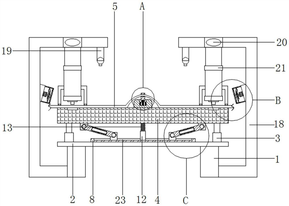
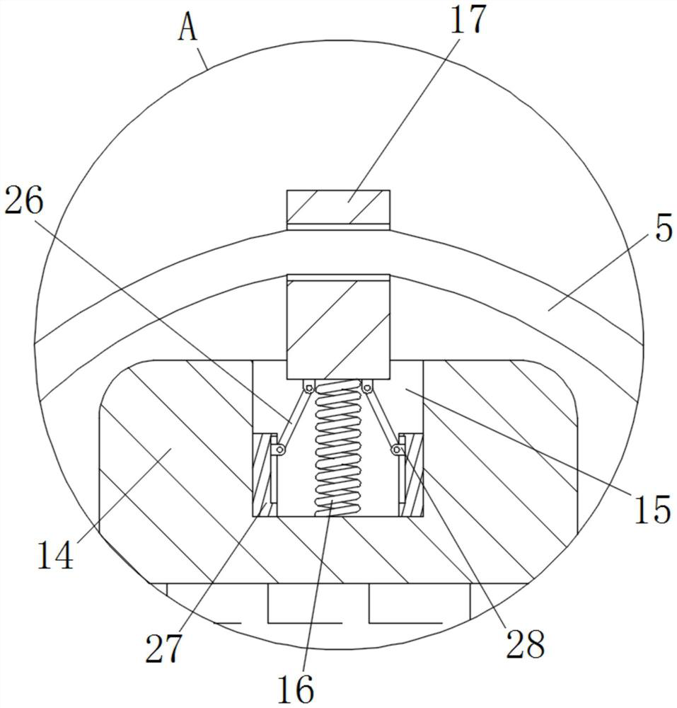
[0018] see Figure 1 to Figure 5 , the present invention provides a technical solution: an efficient and precise wire cutting machine, including a support leg 1, the top of the support leg 1 is fixedly connected with a fixed plate 2, and the top of the fixed plate 2 close to its side is fixedly connected with a telescopic rod 3 , the top of the telescopic rod 3 is fixedly connected with the workbench 4, through the setting of the telescopic rod 3, the situatio...


PUM


Abstract

The invention discloses an efficient and accurate wire cutting machine. The wire cutting machine comprises supporting legs; a fixing plate is fixedly connected to the tops of the supporting legs; telescopic rods are fixedly connected to the top, close to the side surfaces of the fixing plate, of the fixing plate; a workbench is fixedly connected to the tops of the telescopic rods; a wire body is in transmission connection to the upper surface of the workbench; a fixing block is fixedly connected to the lower surface of the workbench; and an upper fixing rod is rotationally connected to the surface of the fixing block through a bearing. According to the wire cutting machine, through cooperation of the structures, the situation that a wire moves in the cutting process is reduced, the cuttingaccuracy of the wire is guaranteed, the situation that the wire is pulled and jumps due to the fact that a wire cutter breaks down is reduced, pressure generated in the wire cutting process of the wire cutter can be decomposed, the situation that the workbench is damaged due to the fact that the wire cutter works for a relatively-long time is relieved, and convenience is brought to work of a user.

Description

technical field [0001] The invention relates to the technical field of wire processing equipment, in particular to an efficient and precise wire cutting machine. Background technique [0002] The wire cutting machine is an electronic product. The wire cutting machine can store 100 sets of data, 6 kinds of wire cutting and stripping modes, and can be used as needed. One PLC controls two stepping motors, one is used to drive the two conveying wheels to rotate to convey the wire, and the other is used to drive the wire groove to rotate, so that the finished product in the wire groove can be dumped into the finished product groove below, and the cutting is controlled by The air pump provides power, and the PLC controls the solenoid valve to supply power to the cylinder to make it press down and cut. Since most of the existing wires are prone to movement during the cutting process, the cutting accuracy of the wires cannot be guaranteed, and a wire cutter is added. If a fault occ...

Claims


Application Information

Patent Timeline
Patent Type & Authority Applications(China)
IPC IPC(8): B21F11/00B21C51/00F25D1/00
CPCB21C51/00B21F11/00F25D1/00
Inventor 刘泽泽
Owner 苏州巨晟旺自动化设备有限公司
Learn More