
Method for sorting casting recycled materials in casting waste

A waste and recycling technology, applied in the direction of solid waste removal, foundry molding equipment, and machinery for cleaning/processing of foundry materials, etc., can solve the problems of difficult recycling and recycling of foundry wastes

Inactive Publication Date: 2021-03-12
马鞍山市绿科环保科技有限公司
View PDF0 Cites 1 Cited by
  • Summary
  • Abstract
  • Description
  • Claims
  • Application Information

AI Technical Summary

Problems solved by technology

[0002] Foundry waste is generally the waste mixture left after processing in the factory workshop of normal processing and manufacturing. It is generally divided into foundry slag, foundry waste sand, fly ash, waste resin sand core and other wastes. Foundry slag is also called molten Slag, which is usually produced in the process of blast furnace metallurgy and floats on the surface of liquid substances such as metals. Its composition is usually mainly oxides such as silica, alumina, calcium oxide and magnesium oxide, and often contains sulfides. And a small amount of metal substances are entrained. Foundry waste sand is waste impurities generated during the casting and forming process, and fly ash is tiny ash particles discharged from the fuel combustion process. The particle size is generally between 1-100 μm, also known as powder. Coal ash or soot, fine solid particles in flue gas produced by fuel combustion, such as fine ash collected from flue gas in coal-fired power plants, etc. After such foundry waste is produced, it is usually foundry slag, foundry waste sand, One or more mixtures of fly ash, waste resin sand core and other substances, if the mixture is not classified, screened and managed, it will be difficult to carry out special and effective recycling, so it is difficult to achieve the reuse of foundry waste

Method used

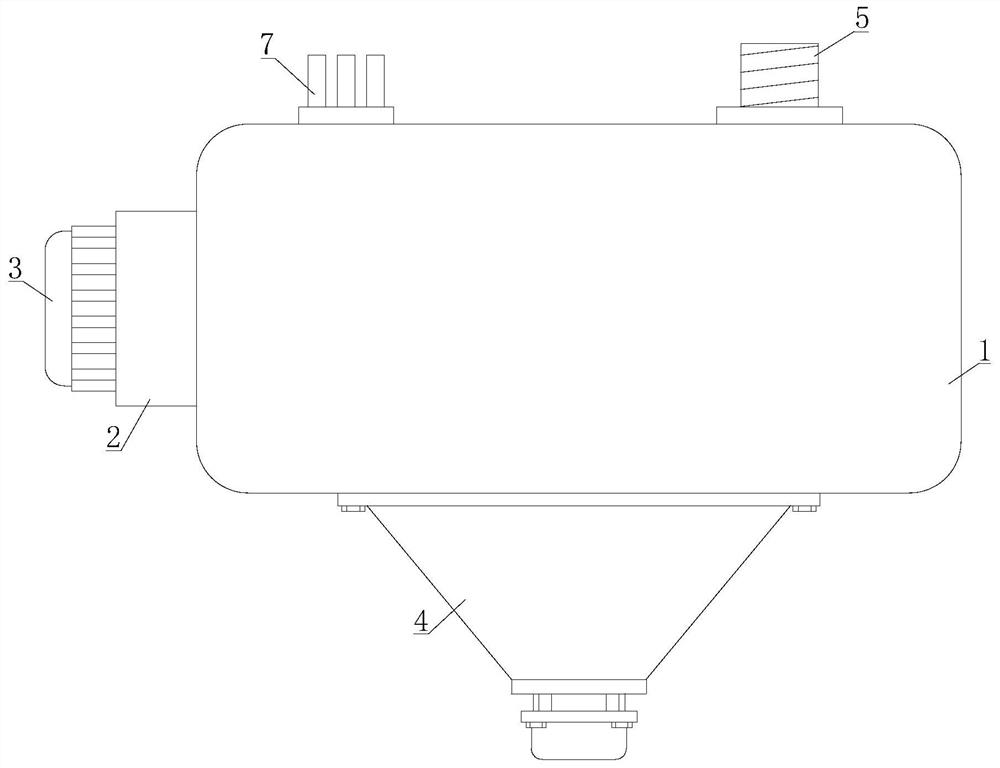
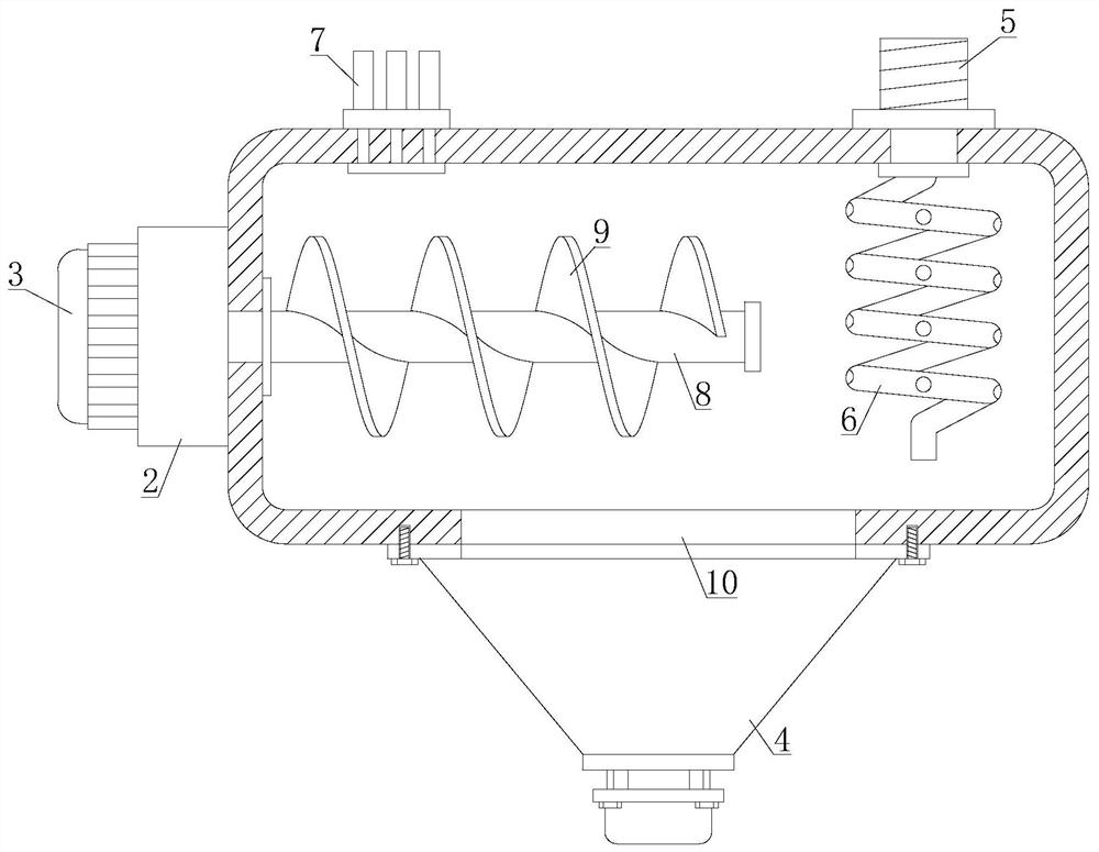

Image

  • Method for sorting casting recycled materials in casting waste
  • Method for sorting casting recycled materials in casting waste
  • Method for sorting casting recycled materials in casting waste

Examples


Embodiment Construction

[0026] The following will clearly and completely describe the technical solutions in the embodiments of the present invention with reference to the accompanying drawings in the embodiments of the present invention. Obviously, the described embodiments are only some, not all, embodiments of the present invention. Based on the embodiments of the present invention, all other embodiments obtained by persons of ordinary skill in the art without making creative efforts belong to the protection scope of the present invention.

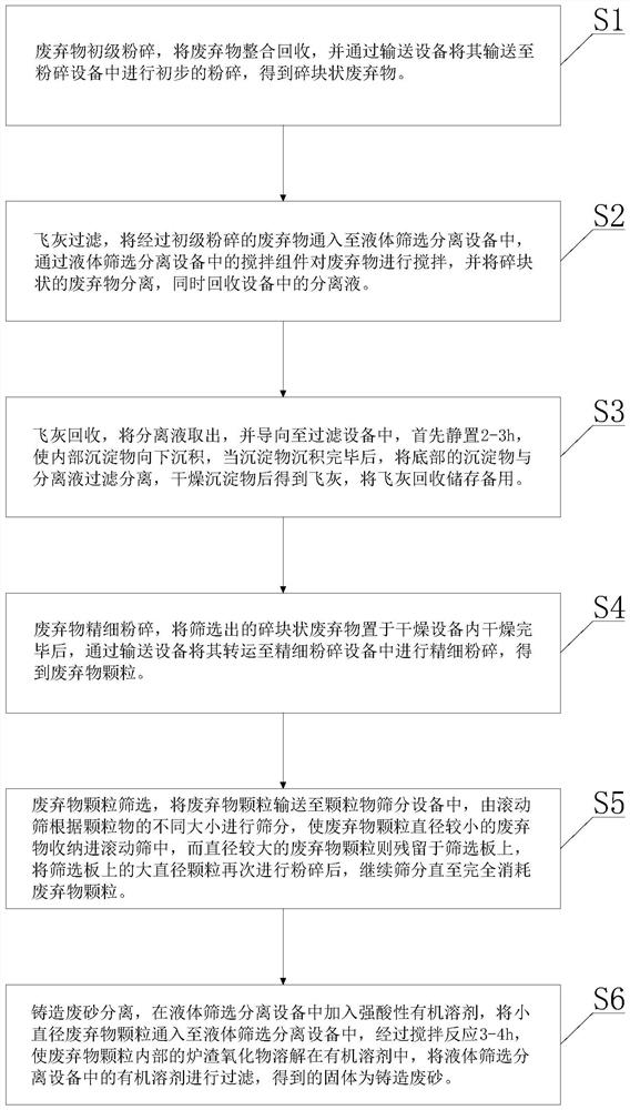
[0027] see figure 1 , a method for sorting foundry waste in foundry waste, comprising the steps of:

[0028] Step 1: Primary crushing of waste, integrating and recycling the waste, and transporting it to the crushing equipment through the conveying equipment for preliminary crushing to obtain fragmented waste;

[0029] Step 2: Fly ash filtration, pass the primary crushed waste into the liquid screening and separation equipment, stir the waste through the stir...


PUM

PropertyMeasurementUnit
Diameteraaaaaaaaaa

Abstract

The invention discloses a method for sorting casting recycled materials in casting waste. The method comprises the steps of waste primary crushing, fly ash filtration, fly ash recovery, waste fine crushing, waste particle screening and separation of casting waste sand. Firstly, after waste is added into crushing equipment to be primarily crushed, fragmented waste is obtained, fly ash existing in the waste and separation liquid form suspension liquid, under the stirring state, a filter screen in a screening hopper is directly used for screening out the fragmented waste, the fragmented waste isfinely crushed, particle screening is conducted through particle screening equipment, screened particles are added into liquid screening and separating equipment again, a strong-acid organic solvent is added into the screening and separating equipment, slag oxide in the waste particles is dissolved by utilizing the organic solvent, and the casting waste sand is screened out; and by means of the method, separation and the recovery of the casting waste are effectively realized, and reutilization of the casting waste is convenient.

Description

technical field [0001] The invention relates to the technical field of casting waste sorting, in particular to a method for sorting foundry waste from foundry waste. Background technique [0002] Foundry waste is generally the waste mixture left after processing in the factory workshop of normal processing and manufacturing. It is generally divided into foundry slag, foundry waste sand, fly ash, waste resin sand core and other wastes. Foundry slag is also called molten Slag, which is usually produced in the process of blast furnace metallurgy and floats on the surface of liquid substances such as metals. Its composition is usually mainly oxides such as silica, alumina, calcium oxide and magnesium oxide, and often contains sulfides. And a small amount of metal substances are entrained. Foundry waste sand is waste impurities generated during the casting and forming process, and fly ash is tiny ash particles discharged from the fuel combustion process. The particle size is gene...

Claims


Application Information

Patent Timeline
IPC IPC(8): B09B3/00B22C5/04B22C5/06
CPCB09B3/00B22C5/04B22C5/06
Inventor 刘涛
Owner 马鞍山市绿科环保科技有限公司
Learn More