
Water-electricity separation type heating drinking trough

A technology of water and electricity separation and drinking trough, which is applied in animal drinking devices, applications, animal husbandry, etc., can solve problems such as loss of bolts and drain plugs, dead corners eaten by animals, and deviation of installation holes, etc., to solve dry burning, solve The effect of animal bites

Pending Publication Date: 2021-03-12
朗诚农业科技(山东)有限公司
View PDF0 Cites 0 Cited by
  • Summary
  • Abstract
  • Description
  • Claims
  • Application Information

AI Technical Summary

Problems solved by technology

[0006] Compared with the prior art, the present invention has the following advantages: it solves the product deformation caused by exposure to the sun in the open air in summer; The problem of internal freezing; Solve the problem that the maintenance personnel of the water tank often encounter the problem that the bolts and drain plugs are lost or eaten by animals when maintaining the water valve; ;Solved the problem that the installers of the water tank often missed the installation holes and could not align when installing large water tanks; solved the problem that the cable was bitten by animals when the heater was used for the drinking water tank without a cover; solved the problem of using 220V for the drinking water tank Safety issues for animals or maintenance personnel when using heaters; solves the problem that water troughs that currently use heaters will dry out

Method used


Image

  • Water-electricity separation type heating drinking trough
  • Water-electricity separation type heating drinking trough
  • Water-electricity separation type heating drinking trough

Examples


Embodiment Construction

[0017] The present invention will be described in further detail below in conjunction with the accompanying drawings.

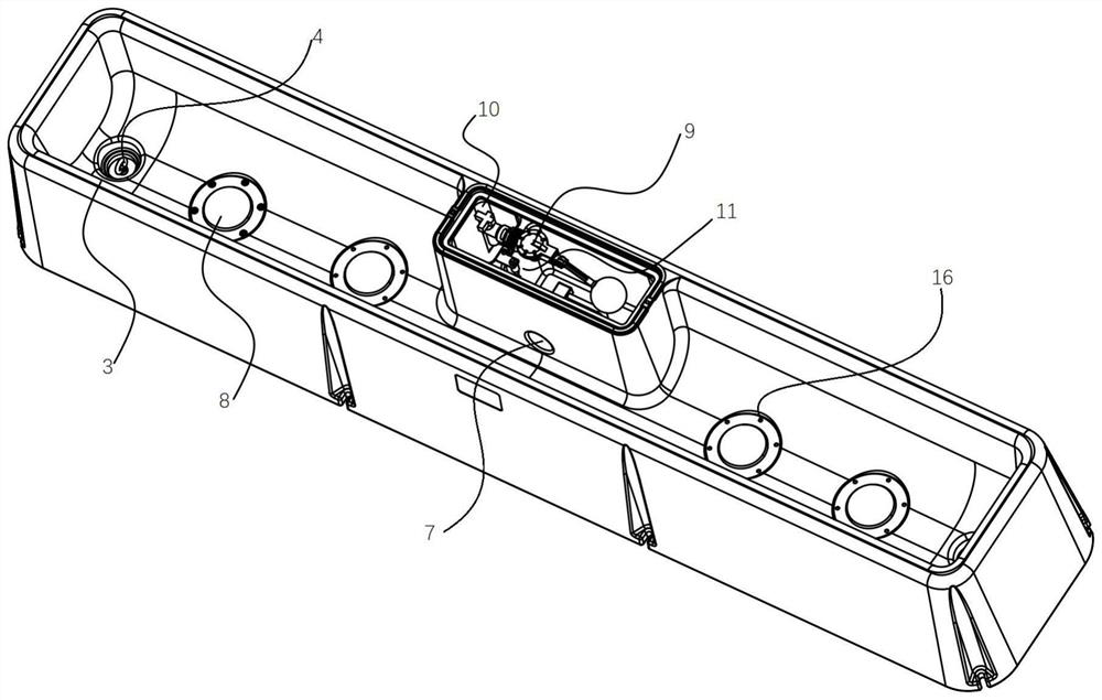
[0018] When the present invention is actually implemented, a water and electricity separation heating drinking water tank includes a tank body 1, a water tank 2 is arranged inside the tank body 1, the cross section of the water tank 2 is U-shaped, and the bottoms of both ends of the water tank 2 are provided with A drain hole 3, a drain valve 4 is installed on the drain port 3, a water valve box 5 is arranged on one side of the middle part of the water tank 2, and a water valve protection cover 6 is installed on the top of the water valve box 5. The side of the water valve box 5 close to the water tank 2 is provided with a water supply port 7, and the bottom of the water tank 2 is provided with a heating plate 8, the number of the heating plates 8 is an even number, symmetrically distributed on both sides of the water valve box 5, the water A differential pre...


PUM


Abstract

The invention discloses a water-electricity separation type heating drinking trough which comprises a trough body, a water trough is arranged in the trough body, the section of the water trough is ina U shape, drain holes are formed in the bottoms of the two ends of the water trough, drain valves are installed at the drain holes, a water valve box is arranged on one side of the middle of the water trough, a water valve protection cover is installed on the top of the water valve box, a water supplementing port is formed in the side, close to the water trough, of the water valve box, a heatingplate is arranged at the bottom of the water trough, a differential pressure water valve is arranged in the water valve box, an angle valve is installed on the differential pressure water valve, a water temperature and water level sensor is arranged on one side of the differential pressure water valve, a heater installation groove is formed in the bottom of the trough body, and a heater is installed in the heater installation groove. Compared with the prior art, the water-electricity separation type heating drinking trough has the advantages that the problems of product deformation, freezing,failure of cleaning of dead corners, slant punching and failure of alignment of mounting holes, bitting of cables by animals, safety guarantee of animals or maintainers when a 220V heater is used in the drinking trough are solved, and the problem that a drinking trough using a heater at present is dry-heated is solved.

Description

technical field [0001] The invention relates to the field of animal husbandry equipment, in particular to a water and electricity separation heating drinking water tank. Background technique [0002] In the early stages of economic development, animal husbandry often appears as a sideline of crop production, which is the so-called "backyard animal husbandry". With the development of the economy, it has gradually become a relatively independent industry in some sectors, such as: laying hen industry, broiler industry, dairy industry, beef cattle industry, pig industry, etc. [0003] Different from self-sufficient livestock breeding, the main characteristics of animal husbandry are centralized, large-scale, and profit-oriented production. Animal husbandry is an extremely important link in the material exchange between human beings and nature. It has a long history in our country and is one of the ancient agricultural projects. Among them, drinking troughs, an important animal ...

Claims


Application Information

Patent Timeline
Patent Type & Authority Applications(China)
IPC IPC(8): A01K7/02
CPCA01K7/027
Inventor 武佩
Owner 朗诚农业科技(山东)有限公司
Learn More