Segmented guide rail type wireless energy transmitting mechanism with signal coil and transmission system

A technology of wireless energy transmission and wireless energy, which is applied in transmission systems, near-field transmission systems, electrical components, etc., can solve the problems of long access time, slow transmission speed and unable to meet the requirements of dynamic charging communication, etc., and achieves a small cross-effect Effect

Inactive Publication Date: 2021-03-09
JIANGSU ELECTRIC POWER CO +2
View PDF2 Cites 4 Cited by
  • Summary
  • Abstract
  • Description
  • Claims
  • Application Information

AI Technical Summary

Problems solved by technology

[0003] However, during the dynamic charging process, the power receiving end is in a state of rapid movement. Traditional communication methods such as WiFi and Zigbee take a long time to access, and the transmission speed is slow and cannot meet the communication requirements of dynamic charging.

Method used


Image

  • Segmented guide rail type wireless energy transmitting mechanism with signal coil and transmission system
  • Segmented guide rail type wireless energy transmitting mechanism with signal coil and transmission system
  • Segmented guide rail type wireless energy transmitting mechanism with signal coil and transmission system

Examples


Embodiment 1

[0027] Embodiment 1 provides a segmented rail-type wireless energy transmitting mechanism with a signal coil, such as figure 1 As shown in the front view, it includes a multi-section guide rail type wireless energy transmitting coil (this embodiment takes 3 sections as an example) and a primary side signal coil overlapping with the multi-section guide rail type wireless energy transmitting coil, wherein each section of guide rail type wireless energy transmitting coil The configuration is a DD-type energy transmitting coil structure, and the primary side signal coil is arranged in parallel with the multi-section guide rail type wireless energy transmitting coil according to the width direction to form a Q-type primary side signal coil structure. Moreover, the primary side signal coil is located above the multi-segment guide rail type wireless energy transmitting coil. A magnetic core structure is laid under the multi-section guide rail type wireless energy transmitting coil. ...

Embodiment 2

[0032] Embodiment 2 provides a segmented rail-type wireless energy transmission system with signal coils, such as Figure 4 As shown in the front view, it includes a transmitting end and a receiving end, wherein the transmitting end is the segmented guide rail type wireless energy transmitting mechanism with a signal coil described in Embodiment 1, the receiving end includes a secondary signal coil and a wireless energy receiving coil, and the secondary The side signal coil is set in a Q-shaped secondary side signal coil structure (the shape can refer to image 3 ), the wireless energy receiving coil is set in a DD type energy receiving coil structure (its shape can refer to figure 2 ).

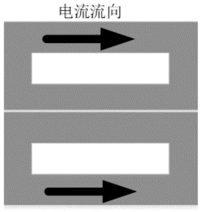
[0033] Among them, the DD-type energy receiving coil structure is composed of two rectangular coils connected in series, and the two rectangular coils are arranged in parallel on the same plane, with the same number of turns but opposite winding directions. The Q-type secondary signal coil...


PUM


Abstract

The invention relates to the technical field of wireless power transmission, and particularly discloses a segmented guide rail type wireless energy transmitting mechanism with a signal coil and a transmission system. The system comprises a transmitting end and a receiving end, wherein the transmitting end is a wireless energy transmitting mechanism and comprises a plurality of segments of guide rail type wireless energy transmitting coils and primary side signal coils overlapped with the guide rail type wireless energy transmitting coils, and each segment of guide rail type wireless energy transmitting coil is of a DD type energy transmitting coil structure; the primary side signal coils are integrally arranged in parallel to form a Q-shaped primary side signal coil structure in the widthdirection relative to the plurality of segments of guide rail type wireless energy transmitting coils; the receiving end comprises a secondary side signal coil and a wireless energy receiving coil, the secondary side signal coil is arranged to be of a Q-shaped secondary side signal coil structure, and the wireless energy receiving coil is arranged to be of a DD-shaped energy receiving coil structure. The energy and signal transmission channels respectively adopt the DD type coil and the Q type coil, and the DD coil and the Q coil can realize natural decoupling, so that parallel transmission ofenergy and signals is realized.

Description

technical field [0001] The invention relates to the technical field of wireless energy transmission, in particular to a segmented guide rail type wireless energy transmitting mechanism with a signal coil and a transmission system. Background technique [0002] Wireless charging technology has the advantages of flexibility, reliability and safety. It is more and more widely used in fields such as drones, home appliances and electric vehicles. In order to achieve optimal system energy efficiency and status monitoring, and improve the performance of the wireless charging system, the wireless charging system often requires communication and interaction information between the primary and secondary sides. [0003] However, during the dynamic charging process, the power receiving end is in a state of rapid movement. Traditional communication methods such as WiFi and Zigbee take a long time to access, and the transmission speed is slow and cannot meet the communication requirement...

Claims


Application Information

Patent Timeline
Patent Type & Authority Applications(China)
IPC IPC(8): H02J50/10H02J50/80H04B5/00
CPCH02J50/10H02J50/80H04B5/0037H04B5/0075
Inventor 殷勇许庆强王成亮肖宇华杨庆胜徐妍王智慧左志平贾亚辉张振
Owner JIANGSU ELECTRIC POWER CO
Why Eureka
Try Eureka