Eureka AIR delivers breakthrough ideas for toughest innovation challenges, trusted by R&D personnel around the world.

An aluminum alloy welded sub-frame formed by hydraulic tube expansion

A technology of aluminum alloy and sub-frame, which is applied to vehicle parts, substructure, transportation and packaging, etc. It can solve the problems of high difficulty in installation and disassembly, increase of body weight, low precision, etc., achieve good vibration isolation effect and reduce operation Difficulty, the effect of improving the rigidity of the connection

Active Publication Date: 2021-10-22
芜湖禾田汽车工业有限公司
View PDF6 Cites 0 Cited by
  • Summary
  • Abstract
  • Description
  • Claims
  • Application Information

AI Technical Summary

Problems solved by technology

[0002] The sub-frame is the bracket that supports the front and rear axles and the suspension. The main purpose is to reduce the transmission of road vibration into the compartment, bring good comfort and turn the suspension into an assembly component, improving the connection stiffness of the suspension system and the versatility of the suspension. , the assembly parts are easy to install, which reduces the assembly cost, but the huge sub-frame will increase the weight of the body, and the installation and disassembly process is relatively difficult due to the weight of the sub-frame itself
[0003] The existing sub-frame uses weight-reducing holes to reduce the weight of the sub-frame, but it will relatively reduce the connection stiffness of the suspension system, which will affect the stability of the car's handling, or use the aluminum alloy material formed by stamping to reduce the weight of the sub-frame. The weight of the frame, but its accuracy is low, and the amount of materials is relatively high, which will affect the overall installation accuracy of the sub-frame, adversely affect the overall performance of the car, and relatively increase the process cost

Method used


Image

  • An aluminum alloy welded sub-frame formed by hydraulic tube expansion
  • An aluminum alloy welded sub-frame formed by hydraulic tube expansion
  • An aluminum alloy welded sub-frame formed by hydraulic tube expansion

Examples


Embodiment Construction

[0023] Next, the technical solutions in the embodiments of the present invention will be described in connection with the drawings of the embodiments of the present invention, and it is understood that the described embodiments are merely the embodiments of the present invention, not all of the embodiments. Based on the embodiments of the present invention, all other embodiments obtained by those of ordinary skill in the art are in the range of the present invention without making creative labor premise.

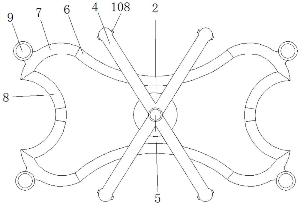
[0024] See Figure 1-6 A hydro-welded aluminum tube forming the sub-frame, the seat 1 includes a shock stable, stable damper seat 2 and the plate 1 from stable composition cushion 3, a cushion 3 is fixedly mounted on the front stabilizer plate 2 , fixed to the back plate 2 is connected to a stable X-type stabilizing guide member 4, X-type stabilizer guide member 2 and the central position of the stabilization plate 4 defines a mounting groove 5, X-shaped guide member form a stabl...


PUM


Abstract

The invention provides an aluminum alloy welded sub-frame formed by hydraulic tube expansion, which belongs to the technical field of sub-frames, and includes a transverse member, a longitudinal member and a connecting piece, and the transverse member and the longitudinal member adopt hydraulic tube expansion forming technology, wherein The transverse member, the connecting member and the longitudinal member are all arc-shaped, and the end-to-end fixed connections are sequentially arranged so that the arc surfaces are opposite to each other. The aluminum alloy welded sub-frame formed by hydraulic expansion tubes, through the hydraulic expansion tube forming technology, forms a large water expansion pressure inside the aluminum alloy profile and interacts with the abrasive tool at one end of the piston shaft to obtain the hydroformed aluminum alloy parts, which is the same as Compared with the aluminum alloy parts formed by traditional stamping, its shape and precision are greatly improved, which not only saves materials, but also reduces the weight of the sub-frame itself, thereby relatively reducing the impact of the weight of the sub-frame on the overall performance of the car. At the same time, it also improves the connection rigidity of the suspension system to ensure the stability of the car handling.

Description

Technical field [0001] The present invention relates to a technical field sub-frame, particularly up welded aluminum tube forming the sub-frame is a hydraulic. Background technique [0002] The sub-frame is supported by front and rear axles, suspension bracket, the main purpose is to reduce the incoming road vehicle cabin vibration bring good comfort and the cartridge member into the suspension, the suspension system to improve the rigidity and versatility of the connection of the suspension , cartridge member easy to install, reduces assembly cost, the sheer weight of the sub-frame of the vehicle body increases, and because the sub-frame to its own weight results in a higher difficulty of the installation process is relatively detached. [0003] Sub-frame using a conventional lightening holes to reduce the weight of the sub-frame, but will reduce the relative connecting stiffness of the suspension system, which will affect the stability of vehicle handling, or welding aluminum a...

Claims


Application Information

Patent Timeline
Patent Type & Authority Patents(China)
IPC IPC(8): B62D21/02B62D29/00
CPCB62D21/02B62D29/008
Inventor 潘海斌潘琦俊胡柏丽赵迎军王超
Owner 芜湖禾田汽车工业有限公司
Why Eureka
Eureka Blog
Learn More