Movable pipe for fabricated wall surface

A movable tube and assembled technology, applied in the field of architectural decoration, can solve the problems of disturbance, no component pressing the dislocation wall panel, affecting the effect of interior decoration, etc.

Pending Publication Date: 2021-03-05
ZHEJIANG YASHA DECORATION
View PDF0 Cites 0 Cited by
  • Summary
  • Abstract
  • Description
  • Claims
  • Application Information

AI Technical Summary

Problems solved by technology

The existing medical equipment belt installed on the bedside wall of the hospital bed has caused great inconvenience to both the medical staff and the patients. When the connector is inserted, it will disturb or hit the patient, or the patient will block the connector on the equipment belt or accidentally get an electric shock, which will cause life-threatening; and if such an exposed equipment belt is installed in an old-age apartment, it will also affect the interior decoration effect , the elderly may also feel disgusted and feel bad when they see the device belt when they live
[0003] The equipment belt is exposed and the panel is mostly opened with side-hung doors, which affects the space inside the sleeve and is inconvenient; or sliding doors generally have two exposed tracks, which is inconvenient to clean
[0004] In the prior art, most of the movable pipes are fixedly connected, unable to achieve rotational connection, and there is no corresponding component that can realize pressing and dislocation to be applied to the installation of wall panels

Method used


Image

  • Movable pipe for fabricated wall surface
  • Movable pipe for fabricated wall surface
  • Movable pipe for fabricated wall surface

Examples


Embodiment 1

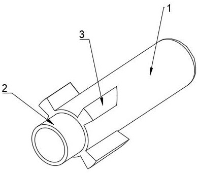
[0030] like Figure 1 to Figure 7 As shown, the present embodiment provides an assembled movable tube for the wall, including a round tube 1, a convex tube 2 and a first wedge-shaped post 3, the convex tube 2 is fixedly connected with the round tube 1, and the diameter of the convex tube 2 is smaller than that of the circular tube. The diameter of the tube 1, the connection between the convex tube 2 and the round tube 1 forms a limiting groove; the outer wall of the convex tube 2 is used to cover the spring so that the spring is against the limiting groove; on the one hand, the spring can be limited , so that the spring can be compressed, on the other hand, the position of the spring can be positioned so that the spring does not deviate from the position.

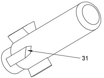
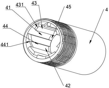
[0031] The round pipe 1 is evenly distributed along the circumference of the pipe wall with four first wedge-shaped columns 3 , the first wedge-shaped columns 3 are slidingly fitted on the sleeve 4 , the first wedge-shaped ...


PUM


Abstract

The invention belongs to the technical field of building decoration, and particularly relates to a movable pipe for a fabricated wall surface. The movable pipe comprises a round pipe, a convex pipe and a first wedge-shaped column, the convex pipe is fixedly connected with the round pipe, the pipe diameter of the convex pipe is smaller than that of the round pipe, and a limiting groove is formed inthe joint of the convex pipe and the round pipe; the outer wall of the convex pipe is used for being provided with a spring in a sleeved mode, so that the spring can abut against the limiting groove;and a plurality of first wedge-shaped columns are evenly distributed on the round pipe in the circumferential direction of the pipe wall, the first wedge-shaped columns are in sliding fit with the sleeve, and each first wedge-shaped column is provided with a wedge-shaped slope which is in contact fit with a pressing head. The first wedge-shaped columns are connected with the sleeve and the pressing head, when force is applied to the pressing head, the movable pipe can be matched in a dislocated mode, when force is applied to the pressing head again, the movable pipe can reset, and the pressing dislocation function can be achieved.

Description

technical field [0001] The invention belongs to the technical field of architectural decoration, and in particular relates to an assembled movable pipe for walls. Background technique [0002] Medical equipment belts are generally installed on the bedside wall in the hospital ward, providing patients with various service facilities such as gas terminals, intercom call systems, data interfaces, lighting or air-conditioning switches, power switches, and bedside lamps. , which is an essential gas terminal control component for central oxygen supply and central suction systems. The existing medical equipment belt installed on the bedside wall of the hospital bed has caused great inconvenience to both the medical staff and the patients. When the connector is inserted, it will disturb or hit the patient, or the patient will block the connector on the equipment belt or accidentally get an electric shock, which will cause life-threatening; and if such an exposed equipment belt is i...

Claims


Application Information

Patent Timeline
IPC IPC(8): E04F13/074E04F13/22E04F13/23
CPCE04F13/0801E04F2290/02
Inventor 丁欣欣丁泽成王文广周东珊操婷武鹏李鹏程
Owner ZHEJIANG YASHA DECORATION
Why Eureka
Try Eureka