X-shaped groove welding process for corrosion-resistant alloy composite tube
A corrosion-resistant alloy, groove welding technology, applied in welding equipment, metal processing equipment, manufacturing tools, etc., can solve the problems of unfavorable corrosion-resistant alloy composite pipe welding process, large amount of filler materials, etc., to improve welding operation efficiency, The effect of saving consumption and improving the success rate of welding
- Summary
- Abstract
- Description
- Claims
- Application Information
AI Technical Summary
Problems solved by technology
Method used
Image
Examples
Embodiment 1
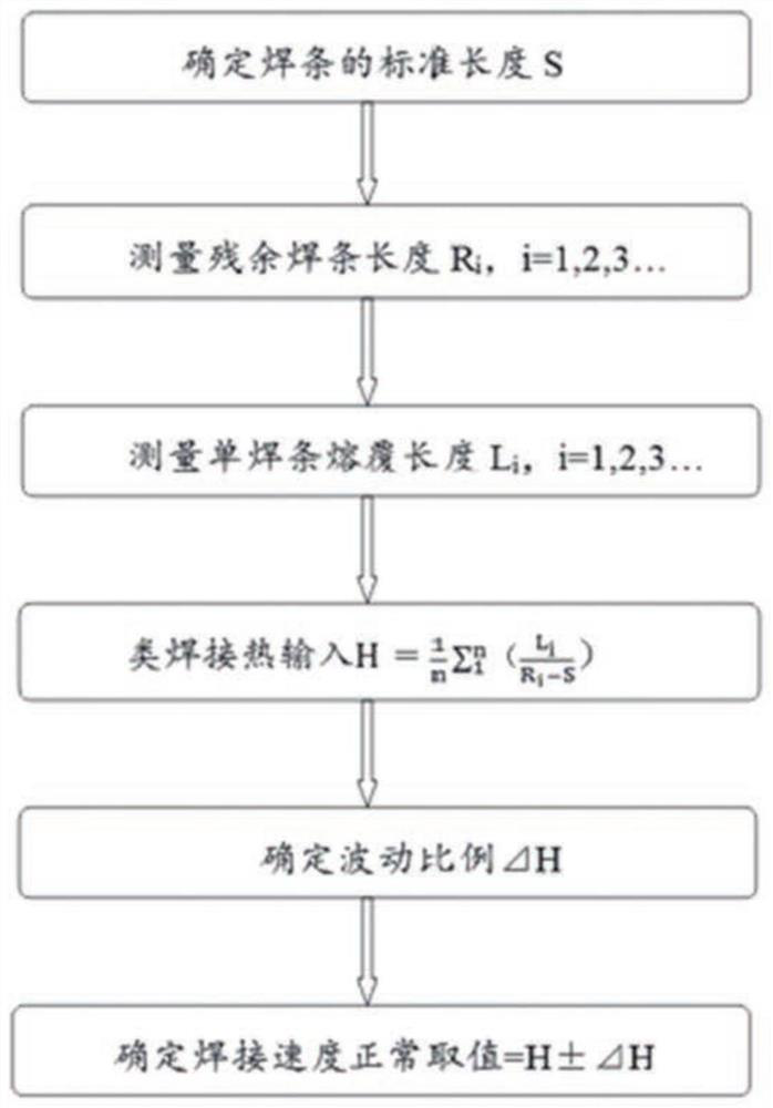
[0054] image 3 A schematic flow chart of the method for visually measuring welding and controlling welding speed by using welding-like heat input in the present invention is shown.
[0055] Such as image 3 As indicated, the control of welding speed by visual measurement of welding using welding-like heat input may include the following steps:
[0056] Obtain the welding-like heat input H of electrode arc welding, and determine the fluctuation ratio ⊿H corresponding to the welding-like heat input. Here, the similar welding heat input is different from the conventional welding heat input, and this type of welding heat input can be used as a new definition to measure the welding heat input. Here, the welding method may be root welding, surfacing welding, filling welding or cover welding.
[0057] Electrode arc welding is performed with similar welding heat input as the welding speed, and visual measurement is used to control the welding speed within the range of H±⊿H. That ...
Embodiment 2
[0069] Figure 5 The experimental data graph of this specific example is shown.
[0070] Such as Figure 5 As shown, the welding process can be controlled simply and intuitively by using the welding-like heat input to realize the visual measurement control of the electrode arc welding method.
[0071] Determine the use of root welding, surfacing welding, filling welding or cover welding. Before use, the standard length of the used electrode is S=450mm. After three sets of tests, after the normal operation is completed, the remaining length of the electrode is R 1 =45mm, R 2 =50mm, R 3 =55mm, the cladding weld length of this electrode is L 1 =L 2 =L 3 =200mm. According to formula The welding-like heat input H=0.5 is obtained.
[0072] The fluctuation ratio is taken as 10%, and the welding heat input is used as the welding speed, and the normal speed range is 0.45 to 0.55. The experimental data are plotted as Figure 5 , then the values between the upper and lower...
Embodiment 3
[0083] The repair process for the weld defect of the corrosion-resistant alloy composite pipe described in this exemplary embodiment requires a qualified welder to carry out the repair process according to the repair welding procedure.
[0084] The process of the present invention first needs to distinguish the defects that appear in the welds of each section to be repaired. The first defect type is arc crater crack defect, and the second defect type is root welding zone or transition layer. The third defect type is Crack defects other than the first and second defect types; the fourth defect type is non-crack defects other than the second defect type.
[0085] Next, different rework processes are respectively adopted for the first, second, third or fourth defect types.
[0086] For the first defect type (that is, arc crater crack defects), since arc crater cracks are thermal cracks, they can be found immediately during the welding process, and such cracks will not cause syste...
PUM
| Property | Measurement | Unit |
|---|---|---|
| thickness | aaaaa | aaaaa |
Abstract
Description
Claims
Application Information
 - Generate Ideas
- Intellectual Property
- Life Sciences
- Materials
- Tech Scout
- Unparalleled Data Quality
- Higher Quality Content
- 60% Fewer Hallucinations
Browse by: Latest US Patents, China's latest patents, Technical Efficacy Thesaurus, Application Domain, Technology Topic, Popular Technical Reports.
© 2025 PatSnap. All rights reserved.Legal|Privacy policy|Modern Slavery Act Transparency Statement|Sitemap|About US| Contact US: help@patsnap.com


