
Structure folding, unfolding and moving device applied to space

A motion device and space technology, applied in electromechanical devices, transportation and packaging, electric components, etc., can solve problems such as rope vibration and failure, and achieve the effects of light weight, low power consumption, and small size

Active Publication Date: 2021-03-02
INST OF MECHANICS - CHINESE ACAD OF SCI
View PDF7 Cites 0 Cited by
  • Summary
  • Abstract
  • Description
  • Claims
  • Application Information

AI Technical Summary

Problems solved by technology

However, there are still many technical difficulties in the tether system. For example, the deployment and recovery process of the tether is very critical. Studies have shown that the tether will continue to vibrate during the free deployment and recovery process. Many missions have failed due to failures in this link.

Method used


Image

  • Structure folding, unfolding and moving device applied to space
  • Structure folding, unfolding and moving device applied to space
  • Structure folding, unfolding and moving device applied to space

Examples


Embodiment 1

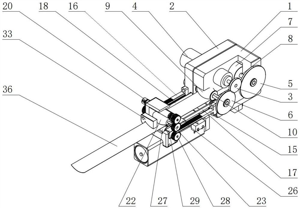
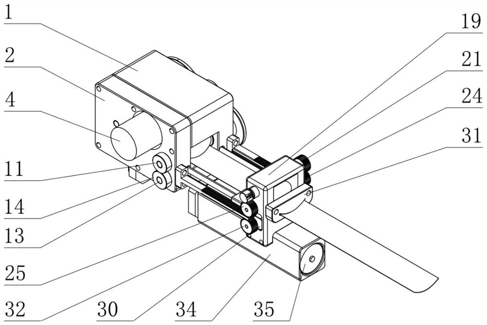
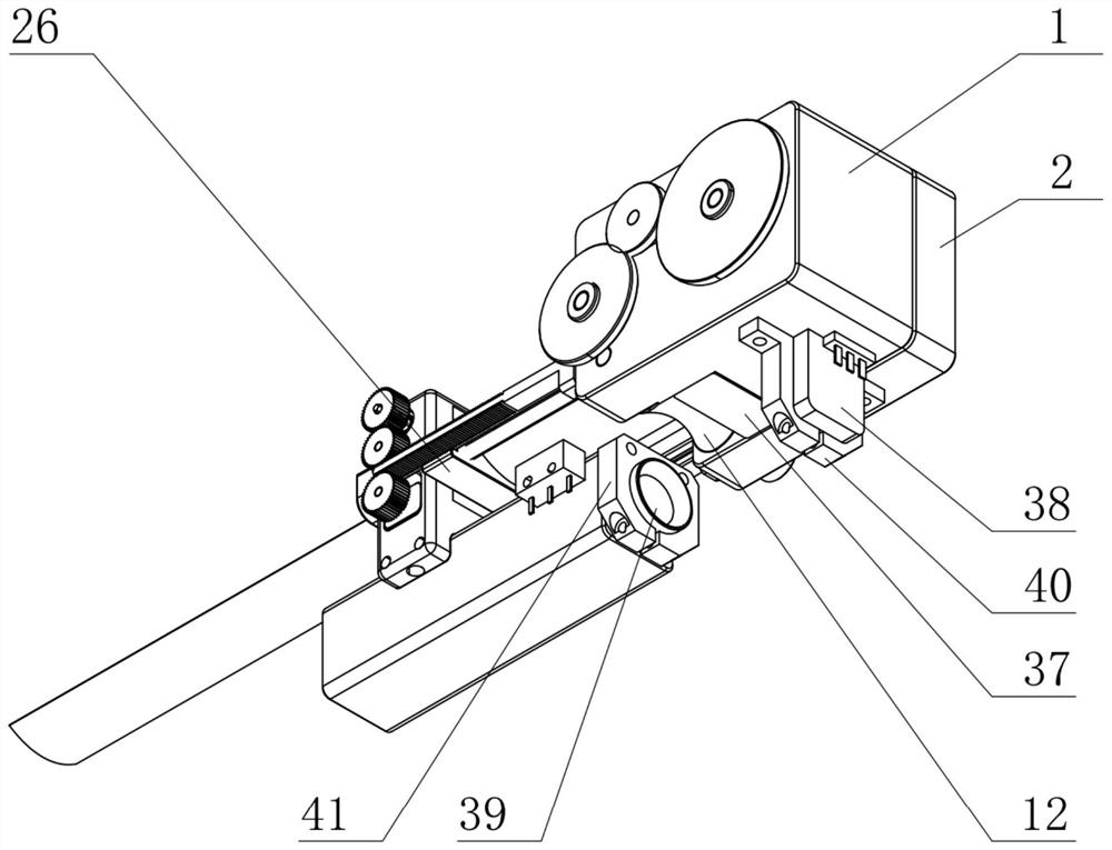
[0029] This embodiment provides a structure retractable and moving device applied in space, the schematic diagram of its three-dimensional structure is as follows figure 1 and figure 2 and image 3 As shown, the device includes:

[0030] A fixed block 1 and an end cover 2, the fixed block 1 and the end cover 2 are relatively fixedly connected, wherein figure 1In the three-dimensional schematic diagram of , in order to clearly show the retractable and moving mechanism of the structure, a part of the fixed block 1 is removed, wherein two hollow round holes are opened in the middle of the fixed block 1, and a rectangular groove is opened in the lower part of the short surface of the fixed block 1, and the rectangular The groove is opened from the top to the second hollow hole, and the other side of the end cover 2 has several holes, among which, the large hole on the end cover 2 fixes the drive motor a4, and the two small holes on the end cover 2 respectively fix the roller sh...

Embodiment 2

[0035] On the basis of Embodiment 1, different from Embodiment 1, when the thin-walled structure 36 is made of hard rubber materials, that is, when a polymer material without rigidity itself is used, the thin-walled structure 36 is heated Afterwards, it can stretch out a structure that is mutually compatible with the calender or forming machine, and then the thin-walled structure 36 itself is tiled and fixed on the cylinder 7, and it passes through the first calender mechanism, and is fed outwards by the rotation of the drive motor b20, in order to Strengthen its rigidity, and bend it through a calendering mechanism. In order to facilitate calendering, a heating device 37 can be installed at the feed inlet. The material limit block 33, through the rotation of the second driving gear 21, the mobile main frame 19 moves along the direction of the rack, and drives the rotation of the remaining driven gears through the intermeshed racks, so that a still structure is formed inside th...


PUM


Abstract

The invention belongs to the technical field of spacecraft equipment, and aims to provide a structure folding, unfolding and moving device applied to space. The device comprises a soft rail folding and unfolding module and a carrying module, and is provided with a fixing block and an end cover, and a hole is arranged to fix a driving motor a, a roller and a calendering mechanism; the carrying module and the soft rail folding and unfolding module are locked through a rack and a sliding rod, and a soft rail of a thin-wall structure is arranged in a rectangular hole of a movable main frame in a penetrating mode; and a process monitoring module is used to record the movement of the soft rail folding and unfolding module and the carrying module to judge the feasibility of the device. The deviceis low in power consumption, small in size and light in weight, and can realize orbit folding and unfolding, satellite transportation and other operations on orbit.

Description

technical field [0001] The invention belongs to the technical field of space vehicle equipment, and in particular relates to a structure retractable and moving device applied in space. Background technique [0002] With the continuous development of human economic activities, new space technology requirements are proposed. For example, with the increase in the number of space objects, new space on-orbit service requirements have emerged. Including on-orbit service, space garbage cleanup, on-orbit maintenance and other related technologies. [0003] Tsiolkovsky first proposed the idea of ​​a space elevator in 1895. A space elevator refers to building a space station on a geosynchronous orbit and connecting it to the ground with a certain flexible cable structure. Astronauts and passengers can take the elevator car to travel between the sky and the earth. The long-running space elevator is currently in the conceptual research phase. Tethered satellite systems (TSS), based ...

Claims


Application Information

Patent Timeline
IPC IPC(8): B64G99/00H02K7/116
CPCH02K7/1163B64G99/00
Inventor 蓝鼎翟思晗王育人
Owner INST OF MECHANICS - CHINESE ACAD OF SCI
Learn More