
Synchronous rectification driving module, synchronous rectification driving circuit and BUCK type voltage reduction circuit

A technology of synchronous rectification and driving modules, which is applied in the direction of converting DC power input to DC power output, electrical components, and adjusting electrical variables. It can solve problems that affect the stability of chip operating voltage, large wafer area, and complex drive circuit structure.

Active Publication Date: 2021-02-26
SHANGHAI XINLONG SEMICON TECH CO LTD
View PDF3 Cites 2 Cited by
  • Summary
  • Abstract
  • Description
  • Claims
  • Application Information

AI Technical Summary

Problems solved by technology

When NMOS is selected as the lower tube, although the power supply voltage generated by the internal LDO (LDO is a low dropout regulator, a low-dropout linear regulator) can be used to drive the NMOS power tube, considering that the NMOS power tube requires a large current when it is turned on , the chip cannot integrate a large-capacity capacitor, and the instantaneous large current will affect the stability of the internal working voltage of the chip. People often use a separate power supply for the NMOS power tube drive circuit in practical applications, and some application products will also use external capacitors. The way to stabilize the power supply voltage of the NMOS power tube built-in drive circuit
The structure of the traditional driving circuit is relatively complex, resulting in large wafer area, high chip cost, and external capacitors lead to many peripheral components of the system, increasing system cost and reducing product competitiveness

Method used


Image

  • Synchronous rectification driving module, synchronous rectification driving circuit and BUCK type voltage reduction circuit
  • Synchronous rectification driving module, synchronous rectification driving circuit and BUCK type voltage reduction circuit
  • Synchronous rectification driving module, synchronous rectification driving circuit and BUCK type voltage reduction circuit

Examples


Embodiment Construction

[0024] In order to facilitate the understanding of those skilled in the art, the present invention will be further described in detail below with reference to specific embodiments.

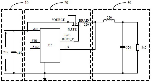
[0025] The embodiment of the present invention first provides a buck-type step-down circuit, please refer to figure 1 , including a power supply circuit 10 , an output circuit 30 and a synchronous rectification drive circuit 20 . One end of the synchronous rectification driving circuit 20 is connected to the power supply circuit 10 , and the other end of the synchronous rectification driving circuit 20 is connected to the output circuit 30 .

[0026] In this embodiment, the power supply circuit 10 includes an input DC power supply VIN and an input filter capacitor 110 connected in parallel.

[0027] The output circuit 30 includes a power inductor 320, an output filter capacitor 330 and a load resistor 340. One end of the power inductor 320 is connected to the power output end of the synchronous r...


PUM


Abstract

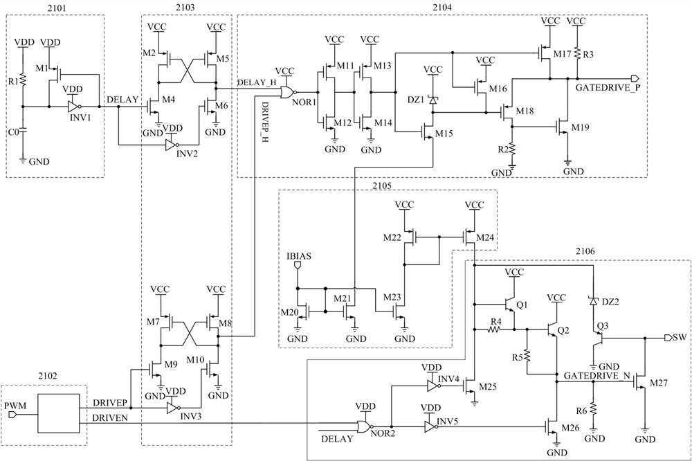
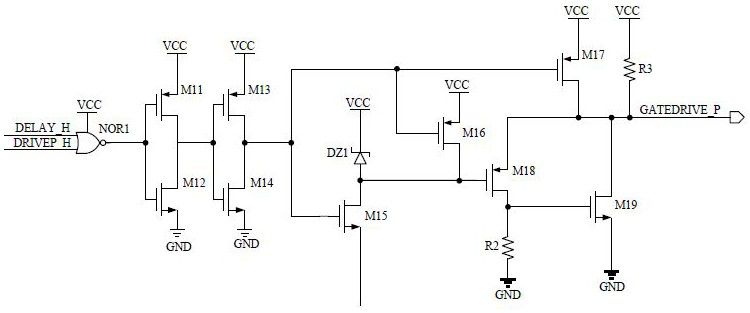
The invention provides a synchronous rectification driving module, a synchronous rectification driving circuit and a BUCK type voltage reduction circuit. A PMOS power tube is used as an upper tube ofthe synchronous rectification circuit, an NMOS power tube is used as a lower tube, and a PMOS power tube driving circuit and an NMOS power tube driving circuit are improved; wherein the PMOS driving circuit is powered by adopting a direct VCCGND; according to the PMOS drive circuit, the voltage of the grid drive end of the PMOS power tube is limited by adopting a method of limiting the voltage ofan M18 grid and enabling M18 and M19 to be matched for discharging, so the circuit structure is simplified while the drive capability is ensured; the NMOS driving circuit stabilizes the voltage of a grid driving end of the NMOS power tube by limiting the voltage of the base of the triode Q1, and ensures that the grid driving end of the NMOS power tube has enough drive capability by amplifying thecurrent flowing out of the M24 through the Q1 and Q2.

Description

technical field [0001] The invention relates to the field of synchronous rectification circuits, in particular to a synchronous rectification drive module, a synchronous rectification drive circuit and a buck-type step-down circuit. Background technique [0002] The power transistors in the step-down circuit include power triodes and power MOS transistors. The power MOS transistors are further divided into PMOS power transistors and NMOS power transistors. For the step-down (BUCK) circuit, the conventional buck-type step-down circuit is divided into asynchronous Rectifier circuit and synchronous rectifier circuit. Although the asynchronous rectifier circuit has low cost, its freewheeling diode has a large freewheeling loss. In order to solve this problem, people have introduced a synchronous rectifier circuit, using a special-purpose The power MOSFET replaces the Schottky freewheeling diode used in the traditional asynchronous rectification circuit. The change of the freewhe...

Claims


Application Information

Patent Timeline
IPC IPC(8): H02M1/08H02M3/155
CPCH02M1/08H02M3/155
Inventor 李瑞平王建虎刘彬
Owner SHANGHAI XINLONG SEMICON TECH CO LTD
Learn More