
Multi-point hanging constant force joint debugging control method and system

A control system and hanging force technology, applied in control/adjustment system, mechanical pressure/force control, non-electric variable control, etc., can solve the problem of under-unloading of gravity, large difference in deviation distribution, over-unloading, etc. problems, to achieve the effect of improving the holding accuracy, improving the uniformity and the synchronization of joint debugging

Active Publication Date: 2021-02-26
SHANGHAI INST OF SATELLITE EQUIP
View PDF11 Cites 0 Cited by
  • Summary
  • Abstract
  • Description
  • Claims
  • Application Information

AI Technical Summary

Problems solved by technology

The published invention patent application (2) "Multi-joint Space Mechanism Gravity Unloading Device", application number: CN201710840028.X, proposes a method of using an active constant tension control unit to realize gravity unloading. The dynamic servo platform realizes the tracking of the displacement of the horizontal plane of the mechanism, so that the suspension rope is always in a vertical state, thereby realizing the gravity unloading of the multi-joint space mechanism, but this method does not involve the synchronization control of multi-point hanging forces and the maintenance of precision of the lifting force. When the multi-joint mechanism is in motion, due to the difference in follow-up speed and unloading force value of each lifting point, there are problems of poor synchronization of multi-point active constant tension adjustment and large difference in deviation distribution. During the unloading process, gravity under-loading at local lifting points is prone to occur. or overloading

Method used


Image

  • Multi-point hanging constant force joint debugging control method and system
  • Multi-point hanging constant force joint debugging control method and system
  • Multi-point hanging constant force joint debugging control method and system

Examples


Embodiment Construction

[0036]The present invention will be described in detail below in conjunction with specific embodiments. The following examples will help those skilled in the art to further understand the present invention, but do not limit the present invention in any form. It should be noted that those skilled in the art can make several changes and improvements without departing from the concept of the present invention. These all belong to the protection scope of the present invention.

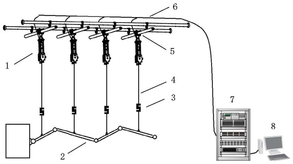
[0037] like figure 1 As shown, the multi-point hanging constant tension system provided by the present invention is used for the gravity unloading of the ground test of the multi-joint mechanism. , Cable 6, PLC motion controller 7, upper computer PC8. Among them, multiple hanging units are installed on multiple groups of two-dimensional guide rail units above through the pulley assembly, and can follow the bottom lifting point to move in the horizontal plane in an active or passive manner to keep the ha...


PUM


Abstract

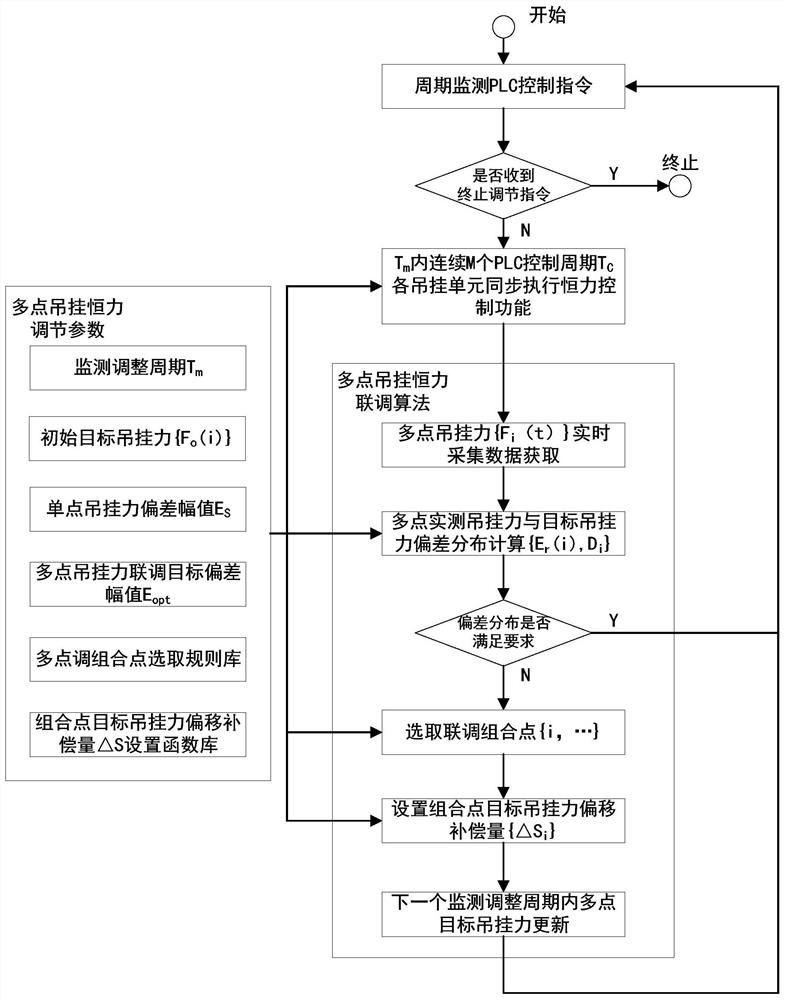
The invention provides a multi-point hanging constant force joint debugging control method and system. The method comprises the steps of enabling an upper computer to calculate the deviation distribution of the hanging force of each hanging point and a preset target hanging force in a monitoring adjustment period, selecting a plurality of corresponding hanging points to form joint debugging combination hanging points according to the characteristics of the deviation distribution; and under the condition that the target hanging resultant force of the joint debugging combination hanging points is kept unchanged, setting the target hanging force offset compensation amount of each hanging point in the joint debugging combination hanging points, and in the next monitoring adjustment period, enabling the upper computer to send the compensated target hanging force of each hanging point to a PLC motion controller, so that each hanging unit controls winding and unwinding of a hanging rope, andthe hanging force of each hanging point is adjusted to a new stable state within the allowable deviation range. According to the invention, constant force maintenance and joint debugging control of hanging at each point are realized, and the distribution uniformity of multi-point hanging force deviation and the synchronism of joint debugging are improved.

Description

technical field [0001] The invention relates to the field of spacecraft ground tests, in particular to a method and system for multi-point suspension constant force joint adjustment control. Background technique [0002] The gravity of the mechanism needs to be unloaded during the ground test of the multi-joint mechanism of the spacecraft, and the function, environmental adaptability and reliability of the test mechanism are simulated in the space gravity environment on orbit. Space gravity environments include zero gravity, microgravity environments, and gravity environments with specific acceleration values. At present, methods such as air flotation method, guide rail-pulley suspension method, and active suspension method are generally used to realize the unloading of the gravity of the mechanism during the ground test of the spacecraft. [0003] The air flotation method utilizes the formation of an air film between the air flotation components and the air flotation table...

Claims


Application Information

Patent Timeline
IPC IPC(8): G05D15/01
CPCG05D15/01
Inventor 刘仁伟侯鹏杨兴谢永权董自瑞李志慧徐艺星董贤达韩哲鑫吴晨
Owner SHANGHAI INST OF SATELLITE EQUIP
Learn More