
A peak hold output system

A peak hold and output system technology, applied in the field of control systems, can solve the problems of short hold time, no response, poor precision, etc., and achieve the effect of convenient debugging, simple circuit structure, and high hold precision

Active Publication Date: 2020-12-29
HUBEI SANJIANG AEROSPACE WANFENG TECH DEV
View PDF8 Cites 0 Cited by
  • Summary
  • Abstract
  • Description
  • Claims
  • Application Information

AI Technical Summary

Problems solved by technology

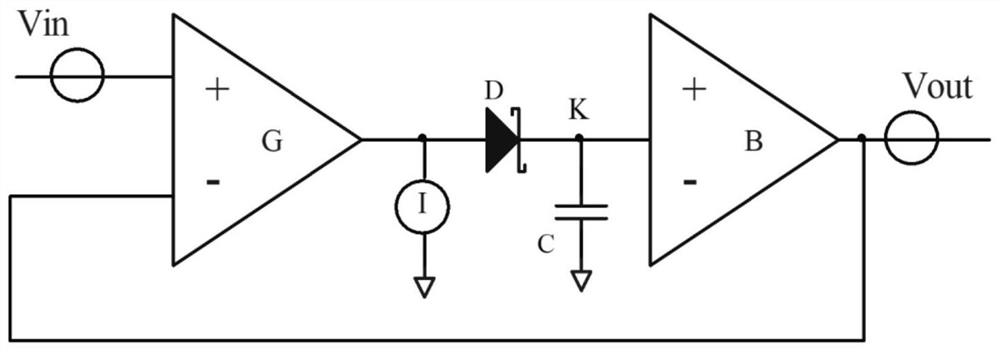
C selects a capacitor with a small value, which can follow the input signal, but the holding time is very short. The main reason is that the leakage current needs to be considered due to the small capacitance value, and the charge on the holding capacitor is relatively small, due to the existence of the leakage current. , in a short time, the charge is discharged
Therefore, the existing transconductance peak hold circuit either does not respond to narrow pulse signals, or the holding accuracy is poor, and it is difficult to achieve high-precision peak hold of narrow pulse signals

Method used


Image

  • A peak hold output system
  • A peak hold output system
  • A peak hold output system

Examples


Embodiment Construction

[0029] In order to make the object, technical solution and advantages of the present invention clearer, the present invention will be further described in detail below in conjunction with the accompanying drawings and embodiments. It should be understood that the specific embodiments described here are only used to explain the present invention, not to limit the present invention.

[0030] In addition, the technical features involved in the various embodiments of the present invention described below can be combined with each other as long as they do not constitute a conflict with each other. The present invention will be further described in detail below in combination with specific embodiments.

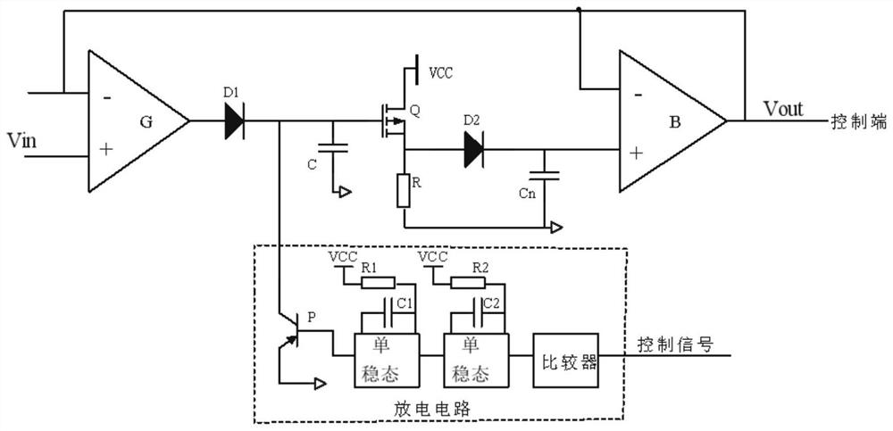
[0031] figure 2 with image 3 They are a schematic diagram and a schematic circuit diagram of a peak hold output system according to an embodiment of the present invention, respectively. Such as figure 2 with image 3 As shown, the system includes an amplification module, a p...


PUM


Abstract

The invention discloses a peak value holding and output system. The peak value holding and output system comprises an amplification module, a peak value holding module, a control module and a discharging module, the amplification module is connected with the peak value holding module, the peak value holding module is connected with external equipment, the control module and the discharging module,the control module is connected with the discharging module, and the amplification module is used for amplifying an input electric signal converted by a photoelectric detector and sending the input electric signal to the peak value holding module; the control module is used for generating a corresponding control signal and sending the corresponding control signal to the discharging module; the discharging module is used for controlling the peak value holding module to conduct peak value holding or discharging resetting; and the peak value holding module is used for following an output signalof the amplification module to generate a peak value holding signal and sending the peak value holding signal to the external equipment, the peak value holding module comprises a first capacitor and asecond capacitor which are connected in parallel, the first capacitor is used for holding the peak value, and the second capacitor is used for reducing a leakage current of the first capacitor, so that the precision of the output signal of the peak value holding and output system is improved.

Description

technical field [0001] The invention belongs to the field of control systems, and in particular relates to a peak hold output system. Background technique [0002] The laser guidance system needs to extract the optical signal from the laser echo for photoelectric conversion, and after signal processing, the position of the relative angle of the target can be calculated, so as to achieve precise strike on the target. In the guidance process, it is necessary to use a laser pulse signal with stable signal wavelength, high monochromaticity, less interference from light and other gases, and high sensitivity. Therefore, narrow laser pulse signals are widely used. The pulse width of this signal is Generally only about 10ns, the frequency is much smaller than ordinary light. [0003] In the laser tracking and guidance system, a four-quadrant photodetector is generally used to extract the optical signal from the laser echo for photoelectric conversion to determine the target orienta...

Claims


Application Information

Patent Timeline
Patent Type & Authority Patents(China)
IPC IPC(8): G01S17/88G01S17/42G01S7/4861
CPCG01S7/4861G01S17/42G01S17/88
Inventor 周辉姜清秀王超程友信王亚飞周奂斌郑晓飞
Owner HUBEI SANJIANG AEROSPACE WANFENG TECH DEV
Learn More