
Powder feeding device for concrete mixing plant

A technology of feeding device and mixing plant, applied in the field of powder feeding device of concrete mixing plant, can solve the problems such as the rotation of the rotating rod and the fan blade is blocked, the labor is consumed, the staff is injured, etc., so as to save power resources, strengthen the Work efficiency, prevent injury effect

Active Publication Date: 2021-02-26
泉州坚石混凝土建材有限公司
View PDF11 Cites 1 Cited by
  • Summary
  • Abstract
  • Description
  • Claims
  • Application Information

AI Technical Summary

Problems solved by technology

[0003] Through retrieval, publication number is that the patent of CN211389535U discloses the powder material feeding device that is used for concrete mixing plant, yet, still there is following technical problem in this device: 1) the position of weighing hopper is higher, and the staff is putting in powder material Sometimes it is necessary to use external tools to raise itself or lift the powder into the inner bucket, which will be very time-consuming and labor-intensive. 2) Long-term work is likely to cause the powder to lose force and cause the staff to be injured. 3) Concrete powder is sometimes doped with some large particles of impurities, and the existing device cannot filter this part of impurities, which will affect the quality of the mixed concrete. Will be extremely labor-intensive and insufficiently picked
[0004] The patent with the publication number CN209453905U discloses a powder feeding device for a concrete mixing station. By adding parts such as a rotating shaft and fan blades, the bulk powder will be broken into the metering system when it enters the feeding hopper. The wall scraper allows the powder on the side wall to be scraped off to enter the metering system. However, the upper opening of the feeding hopper of this device is very large, but the lower discharging cylinder is set smaller in order to stagger with the position of the motor. In this way, when the staff adds a large amount of powder into the existing device, it will be accumulated in the feed hopper due to the limitation of the output of the discharge cylinder, which will easily cause the rotation of the rotating rod and fan blade in the feed hopper to be blocked. , which in turn can lead to damage to the device

Method used


Image

  • Powder feeding device for concrete mixing plant
  • Powder feeding device for concrete mixing plant
  • Powder feeding device for concrete mixing plant

Examples


Embodiment Construction

[0029] In describing the present invention, it should be understood that the terms "center", "longitudinal", "transverse", "length", "width", "thickness", "upper", "lower", "front", " Orientation indicated by rear, left, right, vertical, horizontal, top, bottom, inside, outside, clockwise, counterclockwise, etc. The positional relationship is based on the orientation or positional relationship shown in the drawings, and is only for the convenience of describing the present invention and simplifying the description, rather than indicating or implying that the referred device or element must have a specific orientation, be constructed and operated in a specific orientation, Therefore, it should not be construed as limiting the invention.

[0030] In the description of the present invention, "plurality" means two or more, unless otherwise specifically defined.

[0031]In the description of the present invention, it should be noted that, unless otherwise specified and limited, th...


PUM


Abstract

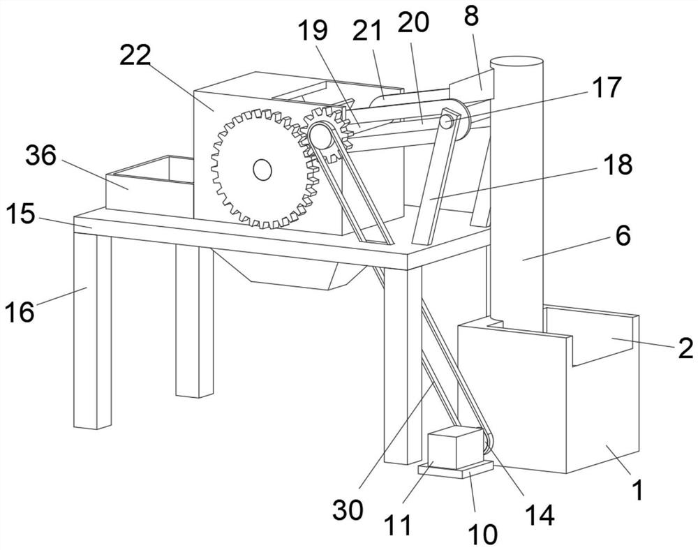
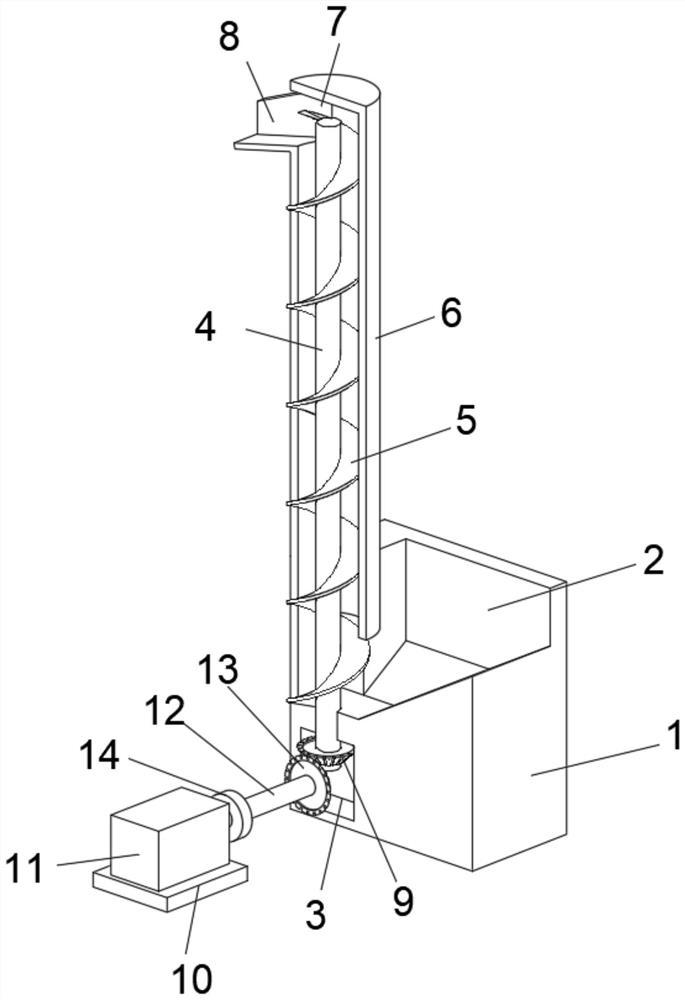
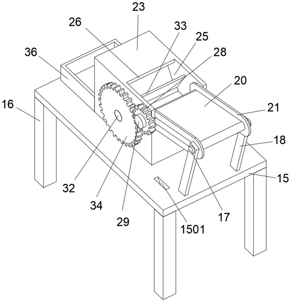
The invention discloses a powder feeding device for a concrete mixing plant, and belongs to the technical field of concrete processing. The powder feeding device for the concrete mixing plant comprises a base, a feeding groove is formed in the middle of the top face of the base, an inner cavity is formed in the position, opposite to the lower portion of the feeding groove, in the base, a middle shaft is arranged on the left side of the bottom face of the feeding groove in a penetrating mode, and the upper portion of the middle shaft is sleeved with an auger blade which is sleeved with a sleeve. An output opening is formed in the left wall of the sleeve, a guide plate is fixedly arranged at the left end of the output opening, and the lower end of the middle shaft penetrates through the bottom face of the feeding groove, extends into the inner cavity and is coaxially and fixedly connected with a bevel gear A. A motor base is arranged on the front side of the base, and a motor is fixedlyarranged in the middle of the top face of the motor base. A fixing plate is arranged above the left side of the base. A discharging assembly is arranged in the middle of the top face of the fixing plate. By means of the powder feeding device, workers are prevented from being hard to lift and convey powder, impurities in the powder can be effectively removed, and practicability is high.

Description

technical field [0001] The invention relates to the technical field of concrete processing, and more specifically relates to a powder feeding device for a concrete mixing station. Background technique [0002] In the large-scale automatic production of concrete, because the concrete mixing device in the concrete mixing plant is usually large in size, a lot of smoke and dust will be generated during the mixing process. If the staff directly adds powder to it, it is necessary to directly Contact with these fumes will greatly endanger the health of the workers, so it is necessary to use a concrete powder feeding device to pour the concrete powder. [0003] Through retrieval, publication number is that the patent of CN211389535U discloses the powder material feeding device that is used for concrete mixing plant, yet, still there is following technical problem in this device: 1) the position of weighing hopper is higher, and the staff is putting in powder material Sometimes it i...

Claims


Application Information

Patent Timeline
IPC IPC(8): B28C9/02B28C5/08B28C5/14B28C7/10B28C7/00B65G45/12
CPCB28C9/02B28C5/0887B28C5/14B28C7/10B28C7/0007B65G45/12
Inventor 刘杨
Owner 泉州坚石混凝土建材有限公司
Learn More