
Integrated circuit pin cutting machine

An integrated circuit and cutting machine technology, which is applied to the parts of grinding machine tools, machine tools suitable for grinding workpiece edges, manufacturing tools, etc., can solve the problem of no post-processing of cutting feet, unstable circuit operation, and inability to use different sizes Integrated circuit board and other problems to avoid circuit instability and improve quality

Pending Publication Date: 2021-02-26
江西世星科技有限公司
View PDF11 Cites 0 Cited by
  • Summary
  • Abstract
  • Description
  • Claims
  • Application Information

AI Technical Summary

Problems solved by technology

[0002] In the integrated circuit manufacturing process, after the chip is soldered, it is necessary to cut off the excess length of the pins. For small and medium-sized integrated circuit manufacturers, there are already mature and applied integrated circuit pin cutting machines, but most of these pin cutting machines have two The big problem is that most of them are specially manufactured for fixed-size integrated circuit boards. They do not have the ability to adjust the width and cannot use different sizes of integrated circuit boards. Second, there is no post-processing of the cut feet after cutting. Cutting defects such as burrs on the pins will affect the overall quality of the integrated circuit, and in severe cases, may lead to unstable operation of the circuit

Method used


Image

  • Integrated circuit pin cutting machine
  • Integrated circuit pin cutting machine
  • Integrated circuit pin cutting machine

Examples


Embodiment Construction

[0018] In order to facilitate the understanding of the present invention, the present invention will be described more fully below with reference to the associated drawings. A preferred embodiment of the invention is shown in the drawings. However, the present invention can be embodied in many different forms and is not limited to the embodiments described herein. Rather, these embodiments are provided so that the disclosure of the present invention will be thorough and complete.

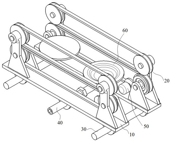
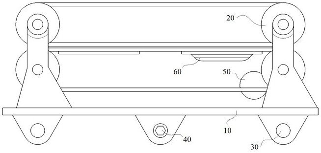
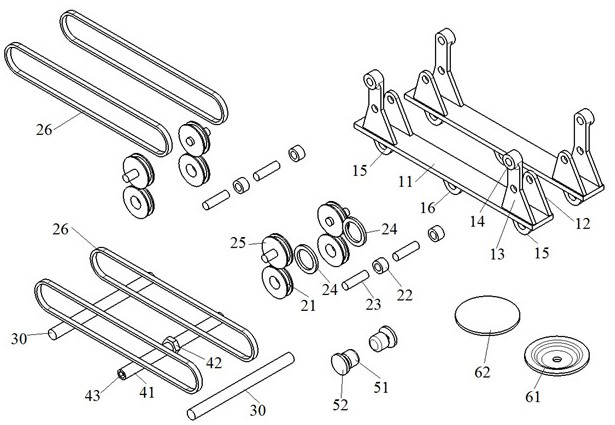
[0019] see Figure 1-Figure 3 The shown integrated circuit foot cutting machine includes a support 10, a transmission part 20, a guide rod 30, an adjustment part 40, a drive part 50 and a cutting part 60, the support 10 has a pair, the transmission part 20 is installed on the support 10, and the guide rod 30 is installed at the bottom of the bracket 10 to guide the movement of the bracket 10. The adjustment part 40 is installed at the bottom of the bracket 10 to regulate the distance between the b...


PUM


Abstract

The invention provides an integrated circuit pin cutting machine, and belongs to the technical field of LED circuit manufacturing. The integrated circuit pin cutting machine comprises a pair of supports, a transmission portion, guide rods, an adjusting portion, a driving portion and a cutting portion; the transmission portion is mounted on the supports; the guide rod is mounted at the bottoms of the supports; the adjusting portion is mounted at the bottoms of the supports; the driving portion is mounted on the supports, connected with the transmission portion and drives the transmission portion to move; and the cutting portion is installed in the middle of the transmission portion. The pair of supports comprise a bottom plate, a short lug piece, a long lug piece, a sleeve, guide lug piecesand a threaded lug piece, and the short lug piece and the long lug piece are arranged at the two ends of the bottom plate respectively. A pair of guide lug pieces are arranged at two ends of the bottom of the bottom plate. The guide rods are mounted in the guide lug pieces. The driving portion comprises a motor and a driving wheel, the motor is installed on the bottom plate and moves along with the supports, and an output shaft of the motor is connected with the driving wheel.

Description

technical field [0001] The invention belongs to the technical field of integrated circuit manufacturing, in particular to an integrated circuit cutting machine. Background technique [0002] In the integrated circuit manufacturing process, after the chip is soldered, it is necessary to cut off the excess length of the pins. For small and medium-sized integrated circuit manufacturers, there are already mature and applied integrated circuit pin cutting machines, but most of these cutting pins have two The big problem is that most of them are specially manufactured for fixed-size integrated circuit boards. They do not have the ability to adjust the width and cannot use different sizes of integrated circuit boards. Second, there is no post-processing on the cut feet after cutting. Cutting defects such as burrs on the pins will affect the overall quality of the integrated circuit, and in severe cases, may lead to unstable operation of the circuit. Contents of the invention [...

Claims


Application Information

Patent Timeline
Patent Type & Authority Applications(China)
IPC IPC(8): B21F11/00B24B9/04B24B41/04
CPCB21F11/00B24B9/04B24B41/04
Inventor 凌丹璐
Owner 江西世星科技有限公司
Learn More