
Cleaning device for medical equipment

A technology for cleaning devices and medical devices, which is applied to cleaning methods using liquids, dry gas arrangements, chemical instruments and methods, etc., and can solve problems such as poor cleaning efficiency, inability to rinse medical devices, and small contact area between medical devices and cleaning devices. , to reduce the effect of cleaning dead corners

Inactive Publication Date: 2021-02-26
贵州睿易通科技有限公司
View PDF6 Cites 5 Cited by
  • Summary
  • Abstract
  • Description
  • Claims
  • Application Information

AI Technical Summary

Problems solved by technology

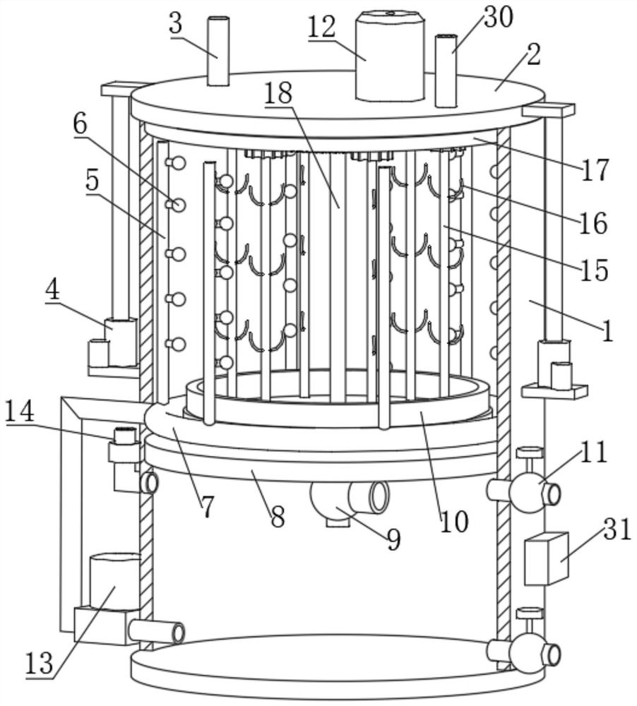
[0005] Aiming at the deficiencies of the prior art, the present invention provides a cleaning device for medical instruments, which can hang the medical instruments for cleaning, and can also soak the medical instruments during flushing. At the same time, the contact area between the medical instruments and the cleaning device is small, and it can also The advantages of accurate flushing of medical instruments solve the problems of large contact area between medical instruments and cleaning devices, prone to cleaning dead angles, inability to accurately flush medical instruments, and poor cleaning efficiency

Method used


Image

  • Cleaning device for medical equipment
  • Cleaning device for medical equipment
  • Cleaning device for medical equipment

Examples


Embodiment 1

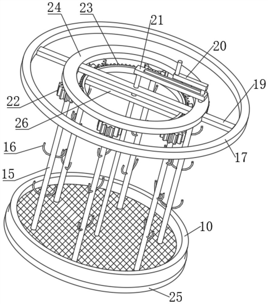
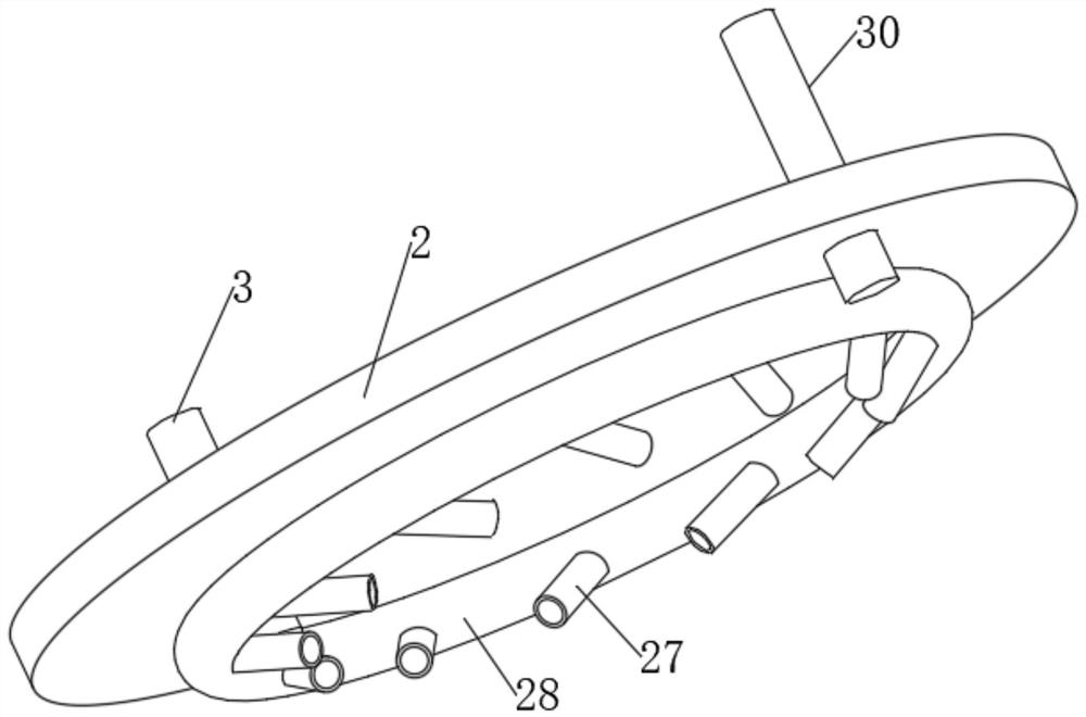
[0026] A cleaning device for medical instruments, comprising a tank body 1, an electromagnetic water valve 9 and a PLC controller 31 fixed on the tank body 1, the upper end of the tank body 1 is provided with an opening, and a cover plate 2 is provided at the edge of the opening, and the cover plate There are two connecting plates symmetrically fixedly connected to the edge of the plate 2, and the lower ends of the two connecting plates are fixedly connected with the electric push rod 4, and the end of the electric push rod 4 away from the connecting plate is fixedly connected with the side wall of the tank body 1, and the cover plate The lower end of 2 is fixedly connected with a circular ring 17, the edge of the circular ring 17 is slidingly connected with the inner edge of the upper opening of the tank body 1, and the inner side of the circular ring 17 is fixedly connected with a connecting rod 19 horizontally, and the center of the rod wall of the connecting rod 19 A rotati...

Embodiment 2

[0028] Embodiment 2: the difference based on Embodiment 1 is;

[0029] The transmission mechanism includes a ring gear 23 that is slidably sleeved on the shaft wall of the rotating shaft 18. The inner side of the ring gear 23 is fixedly connected with a fixed rod 26, and the center of the rod wall of the fixed rod 26 is fixedly connected with the shaft wall of the rotating shaft 18 through a circular opening. The rod wall of the rod 19 is fixedly connected with a positioning ring 24, and the lower end of the positioning ring 24 is vertically rotatably connected with a plurality of evenly distributed support rods 15, and the rod walls of the plurality of support rods 15 are fixedly connected with a gear 22. The gear 22 meshes with the ring gear 23, the rod wall of the support rod 15 is fixedly connected with a plurality of evenly distributed hooks 16, the upper end of the rotating shaft 18 is fixedly connected with a rectangular frame 21, and the rectangular frame 21 is slidably...

Embodiment 3

[0031] Embodiment 3: the difference based on embodiment 1 is;

[0032] The flushing mechanism includes a plurality of conduits 5 vertically fixed on the wall of the annular pipe 7, the plurality of conduits 5 are distributed in an annular array, and the pipe wall of the conduit 5 is fixedly connected with a plurality of evenly distributed water spray heads 6, and the tank body 1 A booster pump 13 is fixedly connected to the lower side of the left end of the booster pump, the input end of the booster pump 13 is fixedly connected to a connecting pipe, one end of the connecting pipe is fixedly connected to the side wall of the tank body 1, and the output end of the booster pump 13 is fixedly connected to a delivery One end of the conveying pipe runs through the side wall of the tank body 1 and is fixedly connected with the pipe wall of the annular pipe 7. The left end of the tank body 1 is fixedly connected with a ventilation pipe 14, and the center of the upper end of the partiti...


PUM


Abstract

The invention relates to the technical field of medical equipment cleaning, and discloses a cleaning device for medical equipment. The cleaning device comprises a tank body, an electromagnetic water valve and a programmable logic controller (PLC) fixed on the tank body, wherein an opening is formed in the upper end of the tank body, a cover plate is arranged at the edge of the opening, and the edge of the cover plate is symmetrically and fixedly connected with two connecting plates; the lower ends of the two connecting plates are fixedly connected with electric push rods, and the ends, away from the connecting plates, of the electric push rods are fixedly connected with the side wall of the tank body; and the lower end of the cover plate is fixedly connected with a circular ring, the edgeof the circular ring is slidably connected with the inner edge of the opening in the upper end of the tank body, and the inner side of the circular ring is transversely and fixedly connected with a connecting rod. According to the cleaning device for the medical equipment, the medical equipment can be hung in the cleaning device to be cleaned, the contact area of the medical equipment and the cleaning device is reduced, the working efficiency of the cleaning device is improved, and the medical equipment can be soaked and effectively flushed during cleaning.

Description

technical field [0001] The invention relates to the technical field of medical instrument cleaning, in particular to a medical instrument cleaning device. Background technique [0002] Medical devices are the general term for medical tools. They are used in clinical operations in hospitals. In addition to conventional surgical instruments, there are also some specialized instruments including sponge forceps, tissue forceps, mosquito hemostatic forceps, and needle forceps. , hemostatic forceps, ordinary dressing forceps, tissue forceps, surgical scissors, scalpel handles, tissue scissors, suture removal scissors, cloth forceps, and deep retractors, etc., the handling of surgical instruments before use and after use should be just right. Avoid over-cleaning to cause damage to the surface of surgical instruments and produce rust. During the operation, surgical instruments contaminated by blood or tissue should be properly wiped. After the operation is completed, they should be ...

Claims


Application Information

Patent Timeline
Patent Type & Authority Applications(China)
IPC IPC(8): B08B3/02B08B3/10B08B13/00A61L2/06F26B21/00
CPCA61L2/06B08B3/022B08B3/041B08B3/10B08B13/00F26B21/004
Inventor 张小勇赵亮
Owner 贵州睿易通科技有限公司
Learn More