
A remote power supply voltage compensation method

A technology of power supply voltage and compensation method, which is applied in the direction of high-efficiency power electronic conversion, electrical components, and adjustment of electrical variables, etc. It can solve problems such as cost increase, equipment overvoltage, and equipment damage, and achieve voltage stability and avoid damage.

Active Publication Date: 2022-05-20
SHENZHEN AEROSPACE NEW POWER TECH
View PDF9 Cites 0 Cited by
  • Summary
  • Abstract
  • Description
  • Claims
  • Application Information

AI Technical Summary

Problems solved by technology

This is effective for scenarios within a range of several meters, but for power supply ranges of hundreds of meters or even longer, this solution requires two additional sampling lines, resulting in difficult wiring and increased costs
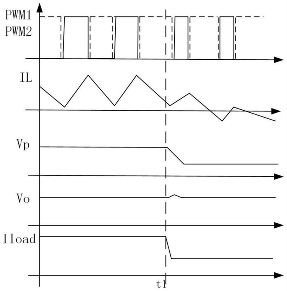
[0004] In addition, ordinary DC sources work in one direction. When the load is switched from heavy load to light load, due to the inhibition of long line impedance, it is difficult to restore the high voltage output on the load side to the normal range in a short time, resulting in overvoltage of the equipment and serious damage to equipment

Method used


Image

  • A remote power supply voltage compensation method
  • A remote power supply voltage compensation method
  • A remote power supply voltage compensation method

Examples


Embodiment Construction

[0020] The present invention will be further described below in conjunction with the description of the drawings and specific embodiments.

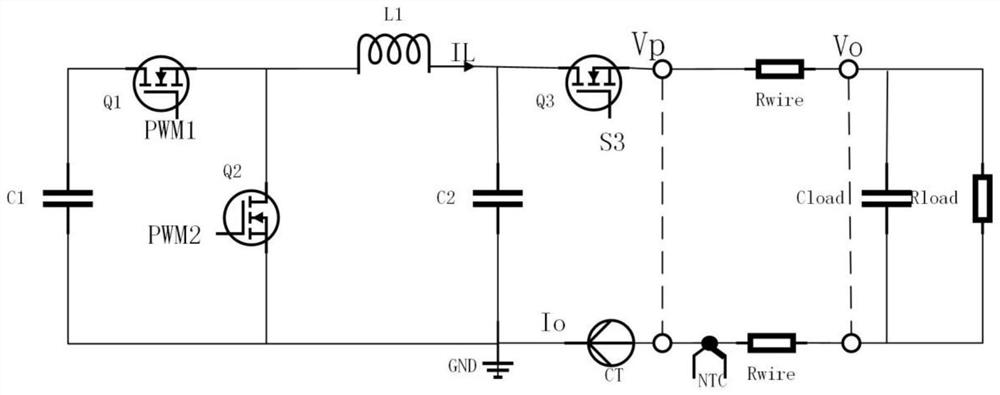
[0021] Such as Figure 1 to Figure 2 As shown, a remote power supply voltage compensation system includes:

[0022] 1. The bidirectional DC converter based on the synchronous BUCK topology is used as the power supply voltage source, of course other bidirectional topologies can also be used;

[0023] 2. MOSFET-based switch Q3 cuts off the power supply of external equipment in time when overcurrent occurs;

[0024] 3. Cable line impedance parameter identification module, used for online detection of line impedance parameters;

[0025] 4. The line temperature acquisition module of the line temperature acquisition module (or other temperature sensors), which is used for temperature compensation of line impedance;

[0026] 5. The DSP control unit completes the function control and realization of the above modules.

[0027] The remote power...


PUM


Abstract

The present invention provides a remote power supply voltage compensation system, including a bidirectional topological DC converter, a MOSFET-based switch Q3, a cable line, a line temperature acquisition module, and a DSP control unit. The output end of the bidirectional topological DC converter is connected to the The input end of the switch Q3 based on the MOSFET is connected, the output end of the switch Q3 based on the MOSFET is connected to one end of the cable line, the other end of the cable line is connected to a remote load, and the line temperature acquisition module is embedded in the In the insulation layer of the cable line, the output end of the line temperature acquisition module is connected with the DSP control unit. The invention also provides a remote power supply voltage compensation method. The beneficial effects of the present invention are: no need for two additional voltage detection lines and their signal conditioning circuits, the load terminal voltage compensation can be realized through voltage compensation through the load current and line impedance parameters, and it is more convenient to apply in long-distance DC power supply systems .

Description

technical field [0001] The invention relates to a voltage compensation system, in particular to a remote power supply voltage compensation system and method. Background technique [0002] In the application of remote high-power DC power supply, as the load increases, the current flowing through the cable increases, and the voltage drop from the output side of the power supply to the remote load will decrease due to the line impedance on the cable over several hundred meters. will increase significantly. If the line impedance voltage drop is not compensated and controlled, it may cause the power supply voltage range of the load to exceed the working area, causing the equipment to stop working or damage the equipment. [0003] At present, the existing technical solution is to collect the voltage of the calibration point, and the differential circuit collects the voltage of the remote device as the feedback input voltage of the controller, so as to control the voltage output o...

Claims


Application Information

Patent Timeline
Patent Type & Authority Patents(China)
IPC IPC(8): H02M3/158
CPCH02M3/158Y02B70/10
Inventor 李海洋许世敏于明伟张斌
Owner SHENZHEN AEROSPACE NEW POWER TECH
Learn More