Adjustment method based on second-order sensitivity matrix method

A technology of sensitivity matrix and adjustment method, applied in the direction of optical components, optics, instruments, etc., can solve problems such as inapplicability, and achieve the effect of less equipment required for detection, high fitting accuracy, and simple process

Inactive Publication Date: 2021-02-23
INST OF OPTICS & ELECTRONICS - CHINESE ACAD OF SCI
View PDF5 Cites 3 Cited by
  • Summary
  • Abstract
  • Description
  • Claims
  • Application Information

AI Technical Summary

Problems solved by technology

However, this method is not suitable for adjustment within a large error range

Method used


Image

  • Adjustment method based on second-order sensitivity matrix method
  • Adjustment method based on second-order sensitivity matrix method
  • Adjustment method based on second-order sensitivity matrix method

Examples


Embodiment Construction

[0042] Embodiments of the present invention will be described in detail below in conjunction with the accompanying drawings.

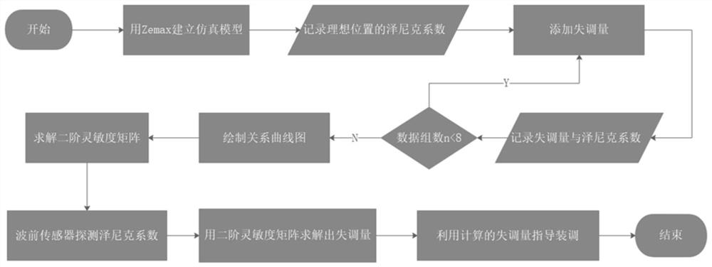
[0043] The present invention is an installation and adjustment method based on the second-order sensitivity matrix method, and the whole method flow is as follows figure 1 As shown, the detailed description is as follows:

[0044] Step 1 Establish the optical system model and optimize:

[0045] Input the structural parameters of the off-axis reflective optical system into the optical simulation software Zemax in turn, establish the optical system model, and optimize the non-critical structural parameters of the optical system until it has the best imaging quality. At this time, the secondary mirror is regarded as ideal Location.

[0046] Step 2 Get the Zernike coefficient

[0047] First record the first eight Zernike coefficients Z of the ideal position in the optical system model 0 n , where 1≤n≤8. Then change the eccentric value and tilt value ...


PUM


Abstract

The invention discloses an adjustment method based on a second-order sensitivity matrix method. The method comprises the steps of: building an off-axis reflection telescope model through Zemax, and obtaining a Zernike coefficient corresponding to a system through changing the spatial positions of other reflectors except a main mirror; obtaining multiple groups of misalignment errors and corresponding Zernike coefficients by repeating the above step, and then obtaining a curve relation function of the misalignment errors and the Zernike coefficients according to the principle of a least squaremethod; and solving a second-order derivative about the offset by using the obtained curve function so as to obtain a second-order sensitivity matrix, and finally guiding the assembling and adjustmentof an off-axis optical system by using the second-order sensitivity matrix. The method is suitable for a large error range, has higher precision than a traditional sensitivity matrix, can be better used for actual adjustment engineering, and improves the final imaging quality of the optical system.

Description

technical field [0001] The invention belongs to the field of optical system adjustment, and specifically relates to an adjustment method based on a second-order sensitivity matrix method, which is based on the Zernike coefficient and the second-order sensitivity matrix to establish the relationship function between the lens misalignment error and the Zernike coefficient of an off-axis optical system and then A method of inversely solving the amount of misalignment according to the changing Zernike coefficient. Background technique [0002] In the fields of astronomical observation, free-space optical communication, and remote sensing of the earth, large-aperture refraction and catadioptric optical systems have chromatic aberration and secondary spectra, so they are subject to certain restrictions. The reflective optical system has no chromatic aberration, can image in a wide spectrum, has a compact optical path structure, and can use free-form surfaces as reflective surfaces...

Claims


Application Information

Patent Timeline
Patent Type & Authority Applications(China)
IPC IPC(8): G02B27/00
CPCG02B27/0012
Inventor 彭起刘柱任戈谭玉凤梁倩
Owner INST OF OPTICS & ELECTRONICS - CHINESE ACAD OF SCI
Why Eureka
Try Eureka