


Quick Research
Generate reliable direction feasibility study reports for your R&D in just a few steps.

Technical Q&A
Discover and master advanced knowledge NOW. Basics, ideas, possibilities, all at once.

Find Solutions
As an expert in R&D theories, this can generate solutions to your technical problems instantly.

Evaluate Feasibility
Analyze your overall solution with one click, know your potential R&D risks in advance.

Monitor Landscape
Get weekly tech updates, stay abreast of the latest tech innovations and key insights.
Oil-water well underground chemical agent controlling and releasing device and control method
A technology of controlled release and control method, which is applied in the field of controlled release devices for downhole chemicals in oil and water wells, can solve the problems of high one-time input, frequent chemical injection, reliability impact, etc. high coefficient effect
- Summary
- Abstract
- Description
- Claims
- Application Information
AI Technical Summary
Problems solved by technology
Method used
Image

Examples
Embodiment 1
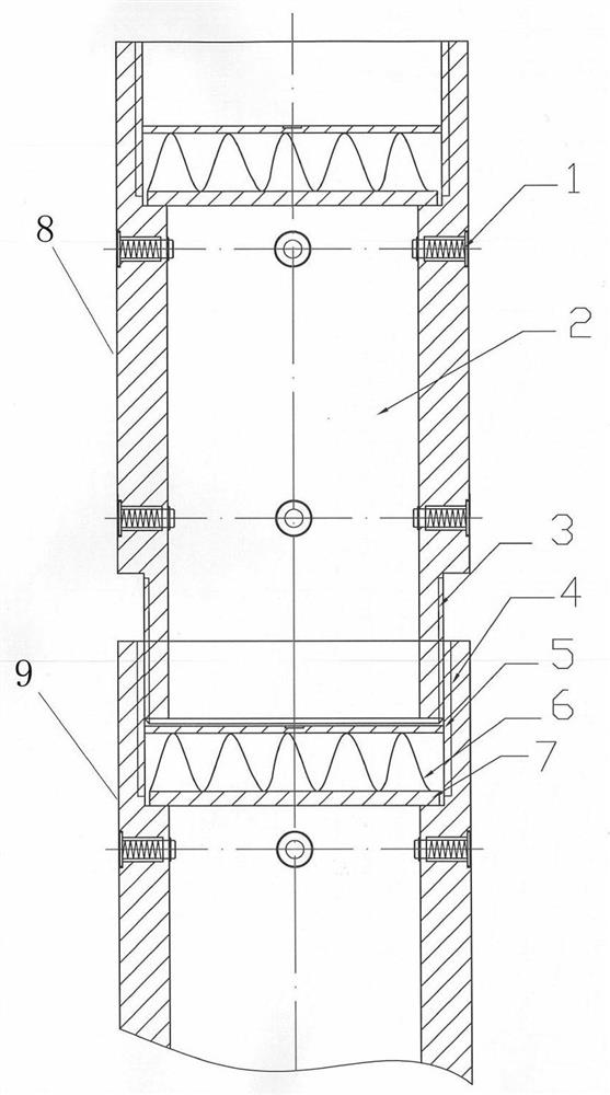
[0038] refer to figure 1 , an oil and water well downhole drug control release device, at least including a first drug storage sub-joint 8 and a second drug storage sub-joint 9, the first drug storage sub-joint 8 and the second drug storage sub-joint 9 are both along the middle of the length direction A through hole is opened, one end of the first drug storage short joint 8 is connected to one end of the second drug storage short joint 9, and the connection between one end of the first drug storage short joint 8 and one end of the second drug storage short joint 9 A soluble partition 7 is also arranged between the end faces, and the through-hole cavity inside the first drug storage nipple 8 above the soluble partition 7 is the drug storage chamber 2 .
[0039] In the above-mentioned embodiment, when lowering the controlled drug release device, the required drug is first added to the drug storage cavity 2 in the first drug storage joint 8 located above, and then the entire firs...
Embodiment 2
[0041] refer to figure 1 , Further, an energy storage mechanism is provided above the soluble partition 7, and a fixed limit ring 5 is provided above the energy storage mechanism.
[0042] Further, the energy storage mechanism is a ring structure, and the outer diameter of the energy storage mechanism of the ring structure is equal to the diameter of the through hole in the middle of the first medicine storage short joint 8 and the second medicine storage joint 9, and the fixed limit The ring 5 is a conical ring, its conical surface is set towards the direction of the energy storage mechanism, and the outer diameter of the conical ring is 3-5mm larger than the diameter of the through hole in the middle of the first drug storage sub-joint 8 and the second drug storage sub-joint 9 .
[0043] In the above-mentioned embodiment above the soluble partition 7, the lower end of the first drug storage nipple 8 is provided with an energy storage mechanism in contact with the top of the ...
Embodiment 3
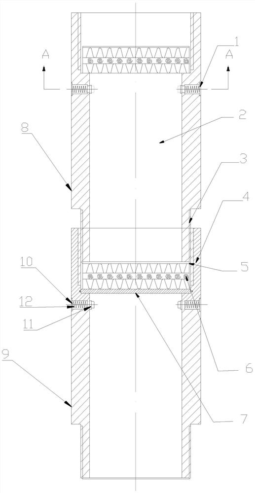
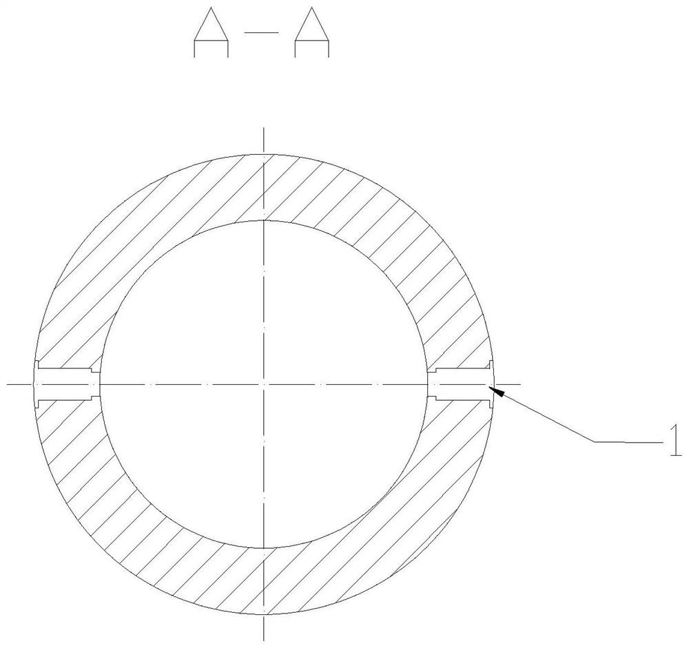
[0046] Further, refer to figure 1 and figure 2 , the first drug storage sub-section 8 and the second drug storage sub-section 9 are both circular cylindrical structures, and one end of the first drug storage sub-section 8 and the second drug storage sub-section 9 is provided with internal threads The first connecting head 4 of the first drug storage joint 8 and the other end of the second drug storage short joint 9 are provided with a second connecting head 3 which is an external thread, and the first connecting head 4 and the second connecting head 3 are both It communicates with the through hole in the middle of the first drug storage short joint 8 and the second drug storage short joint 9, the second connection head 3 of the first drug storage short joint 8 and the first connection head of the second drug storage short joint 9 4 threaded connections.
[0047] In the above-mentioned embodiment, the first drug storage sub-section 8 and the second drug storage sub-joint 9 a...
PUM
 Abstract
Description
Claims
Application Information
 - R&D Engineer
- R&D Manager
- IP Professional
- Industry Leading Data Capabilities
- Powerful AI technology
- Patent DNA Extraction
Browse by: Latest US Patents, China's latest patents, Technical Efficacy Thesaurus, Application Domain, Technology Topic, Popular Technical Reports.
© 2024 PatSnap. All rights reserved.Legal|Privacy policy|Modern Slavery Act Transparency Statement|Sitemap|About US| Contact US: help@patsnap.com