
Polishing device for new energy automobile hub machining

A technology for new energy vehicles and polishing devices, applied in grinding/polishing safety devices, grinding drive devices, metal processing equipment, etc. Improve the grinding effect, improve the polishing efficiency, improve the effect of the polishing effect

Inactive Publication Date: 2021-02-23
李登进
View PDF1 Cites 8 Cited by
  • Summary
  • Abstract
  • Description
  • Claims
  • Application Information

AI Technical Summary

Problems solved by technology

[0004] But above-mentioned device also has the following problems in use: the first, this device can only be polished the top surface of wheel hub, can not polish the edge of wheel hub top surface, causes burr still to exist on the top surface of wheel hub after polishing, and polishing effect is not good , affecting the appearance and normal use of the hub. Second, the device cannot collect the dust generated by polishing, so that the generated dust is scattered on the processing device and in the air, which affects the subsequent polishing of other hubs, and will affect the operator's body. Third, the device cannot polish both sides of the hub, and needs to be assisted by the operator, which leads to a decrease in polishing efficiency and is prone to accidentally injuring the operator

Method used


Image

  • Polishing device for new energy automobile hub machining
  • Polishing device for new energy automobile hub machining
  • Polishing device for new energy automobile hub machining

Examples


Embodiment Construction

[0027] In order to make the object, technical solution and advantages of the present invention clearer, the present invention will be further described in detail below in conjunction with the accompanying drawings and embodiments. It should be understood that the specific embodiments described here are only used to explain the present invention, not to limit the present invention.

[0028]In describing the present invention, it should be understood that the terms "longitudinal", "transverse", "upper", "lower", "front", "rear", "left", "right", "vertical", The orientations or positional relationships indicated by "horizontal", "top", "bottom", "inner", "outer", etc. are based on the orientations or positional relationships shown in the drawings, and are only for the convenience of describing the present invention, rather than indicating or It should not be construed as limiting the invention by implying that a referenced device or element must have a particular orientation, be ...


PUM


Abstract

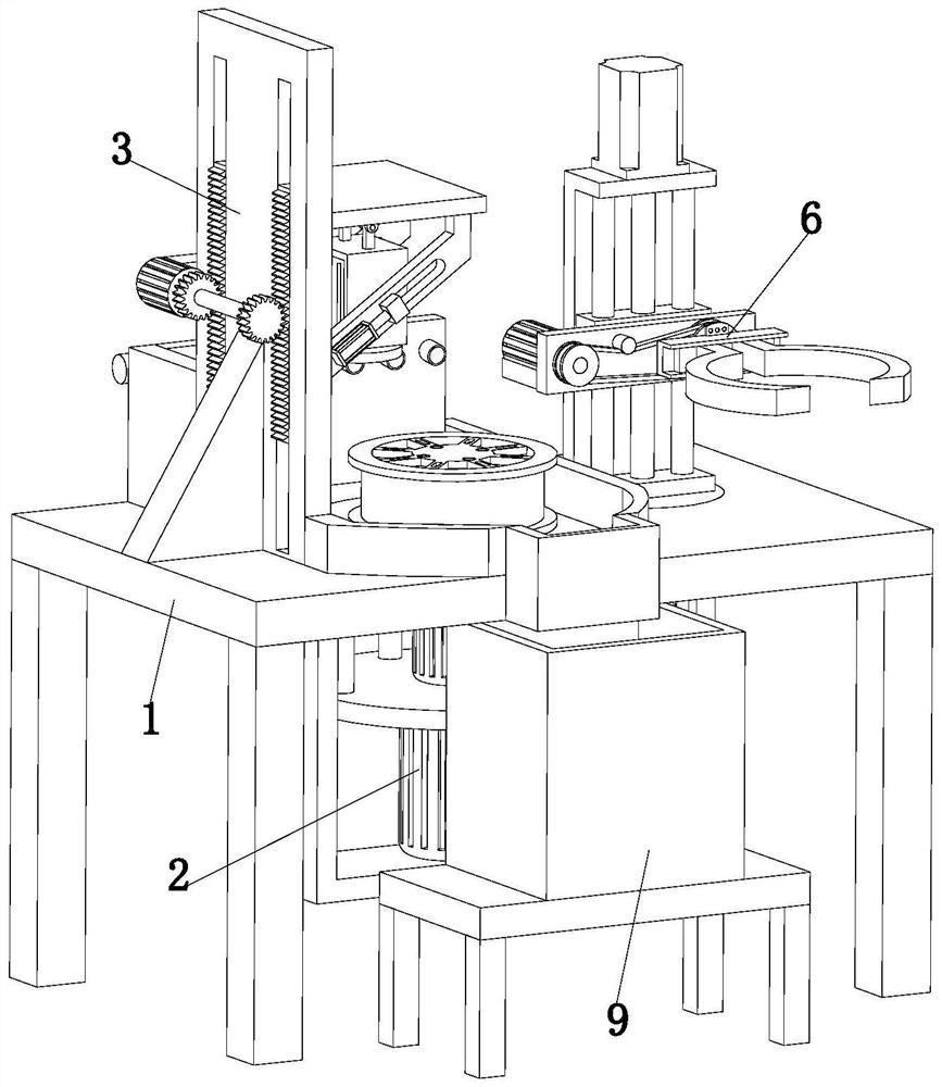
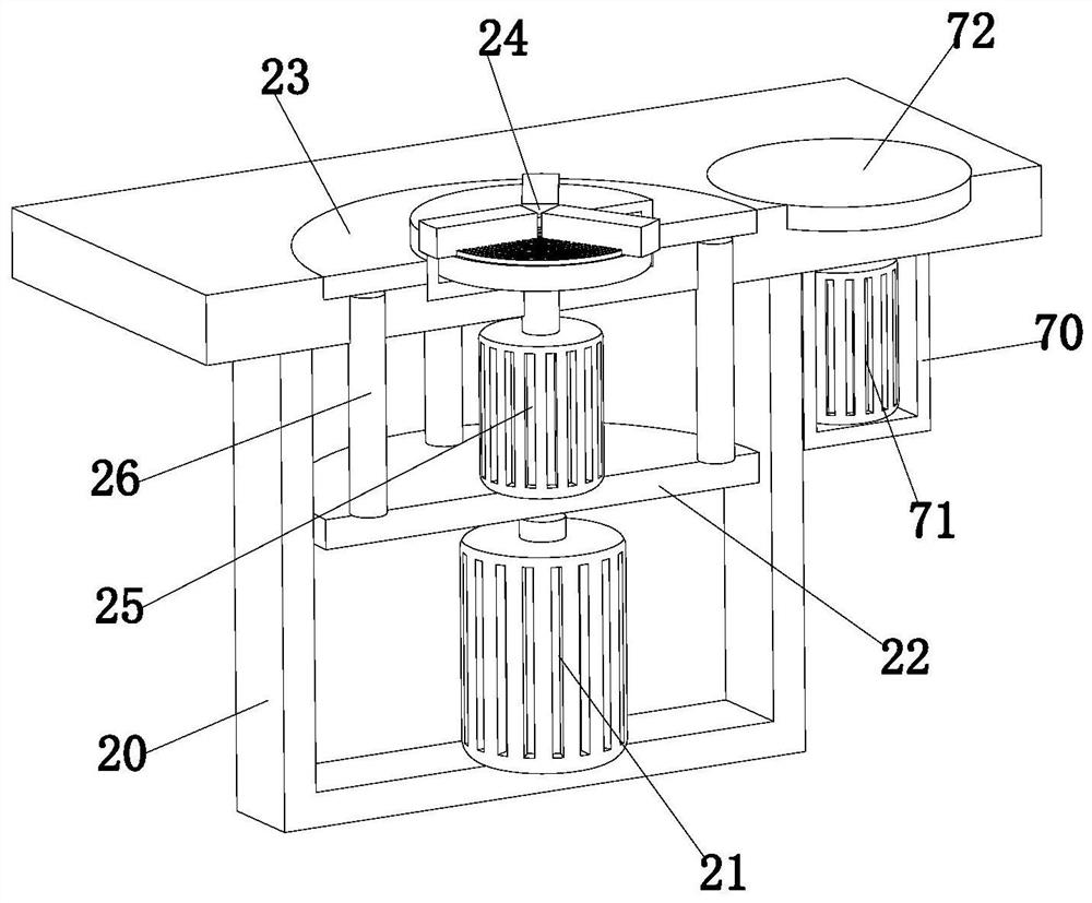
The invention relates to the technical field of automobile accessory machining, in particular to a polishing device for new energy automobile hub machining. The device comprises a machining table, a fixed rotating device, a polishing device, an overturning device and a dust collecting device, the machining table is arranged on a horizontal plane, and the fixed rotating device is clamped on the machining table; and the polishing device comprises a grinding component and an angle adjusting component, the grinding component is installed on the machining table, the grinding end of the grinding component right faces the fixed rotating device, the angle adjusting component is arranged on the grinding component, the overturning device comprises a driving component and an overturning component, the driving component is clamped on the machining table, the overturning component is arranged on the driving component, and the dust collecting device is arranged on the machining table. According to the polishing device, through mutual cooperation operation of all the devices, the two faces of a hub can be automatically overturned and polished, the hub polishing efficiency is improved, the polishing effect is improved, the hub quality is improved, and the attractiveness of the hub is improved.

Description

technical field [0001] The invention relates to the technical field of auto parts processing, in particular to a polishing device for processing new energy automobile wheel hubs. Background technique [0002] The cylindrical metal part used to support the tire with the axle as the center in the car tire is the part where the axle is installed in the center of the wheel, and is an important part connecting the brake disc, wheel disc and half shaft, so the inner profile of the tire supports the drum of the tire The center of the shape is the part mounted on the shaft, which is called the hub. [0003] For example, the patent with the publication number CN110434746A relates to a polishing device for new energy automobile wheel hub processing, including a chassis, a motor is fixedly connected to the left side of the inner cavity bottom of the chassis, and a first bevel gear is fixedly connected to the output end of the motor. The right side of the first bevel gear is meshed wit...

Claims


Application Information

Patent Timeline
IPC IPC(8): B24B29/02B24B41/06B24B47/22B24B47/12B24B41/04B24B47/20B24B55/06B24B55/12
CPCB24B29/02B24B41/04B24B41/06B24B47/12B24B47/20B24B47/22B24B55/06B24B55/12
Inventor 李登进
Owner 李登进
Learn More