Model prediction method, system and device with multi-level inverter and storage medium
A three-level inverter and model prediction technology, applied in the field of micro-grid, can solve the problems of large influence on the stable operation of the power grid, unsatisfactory control effect, short service life, etc., achieve fast transient response, maintain stable and efficient operation, Effect of High Stability Margin
- Summary
- Abstract
- Description
- Claims
- Application Information
AI Technical Summary
Problems solved by technology
Method used
Image
Examples
Embodiment 1
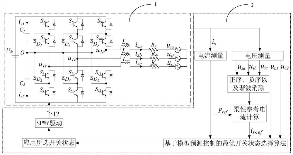
[0051] see figure 1 , the model prediction system of the present invention includes a diode-clamped three-level inverter 1 and a control unit 2 . The control unit 2 includes a current measurement module, a voltage measurement module, a harmonic elimination module, a flexible reference current calculation module, a model predictive control algorithm module and a switch state application module. The current measurement module is used to extract the current value of the grid side; the voltage measurement module is used to extract the voltage value of the grid side; the harmonic elimination module is used to eliminate the positive sequence and negative sequence harmonic components of the measured voltage; flexible reference current The calculation module is used to generate the reference current required by the control system; the model predictive control algorithm module is used to track the reference current and balance the DC measured capacitor voltage; the switch state applica...
Embodiment 2
[0053] Except for the following content, all the other contents are the same as in Example 1.
[0054] Such as figure 1 As shown, the diode-clamped three-level inverter 1 includes a DC input voltage source, 2 input capacitors, 12 power switch tubes, 6 diodes, 3 filter inductors, 3 load resistors and a three-phase input on the grid side Voltage.
[0055] where the input capacitance C 1 One terminal with input capacitor C 2 The connection point is point O, and the other end is connected to the positive pole of the voltage source and the power switch tube S 1 , S 5 , S 9 collector, the input capacitor C 2 The other end is connected to the negative pole of the voltage source and the power switch tube S 4 , S 8 , S 12 The emitter of the power switch tube S 1 The emitter is connected to the power switch tube S 2 The collector of the power switch tube S 2 The emitter is connected to the power switch tube S 3 The collector of the power switch tube S 3 The emitter is conn...
PUM
 Abstract
Description
Claims
Application Information
 - Generate Ideas
- Intellectual Property
- Life Sciences
- Materials
- Tech Scout
- Unparalleled Data Quality
- Higher Quality Content
- 60% Fewer Hallucinations
Browse by: Latest US Patents, China's latest patents, Technical Efficacy Thesaurus, Application Domain, Technology Topic, Popular Technical Reports.
© 2025 PatSnap. All rights reserved.Legal|Privacy policy|Modern Slavery Act Transparency Statement|Sitemap|About US| Contact US: help@patsnap.com


