
A Large Field of View High Efficiency Fiber Coupling System

A fiber-coupled, high-efficiency technology, applied in the field of optical lens design, can solve the problems of limiting the field of view of fiber couplers, unsatisfactory, and small coupling field of view, achieving volume and weight advantages, improving imaging, increasing range effect

Active Publication Date: 2022-07-05
BEIJING INST OF AEROSPACE CONTROL DEVICES
View PDF0 Cites 0 Cited by
  • Summary
  • Abstract
  • Description
  • Claims
  • Application Information

AI Technical Summary

Problems solved by technology

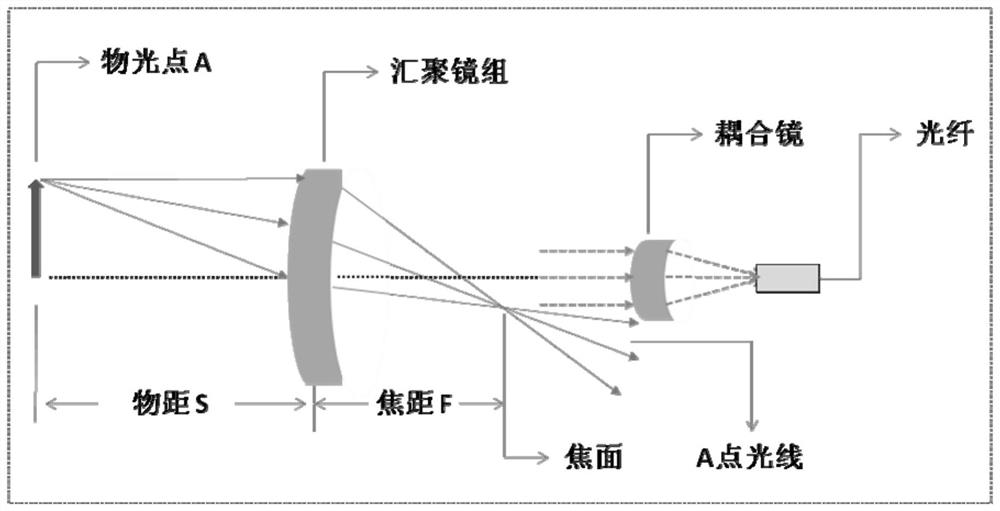
Existing fiber coupling lenses are designed for high coupling efficiency according to the numerical aperture NA of the fiber core, but the coupling field of view is small, usually the fiber NA=0.22, and the field of view of the coupling lens that can be designed generally does not exceed 2mrad. In fact, the better the coupling lens matches the NA value of the fiber, the higher the coupling efficiency will be, which limits the field of view of the fiber coupler
[0003] With the development of detection technology in the new system, the demand for high-efficiency fiber-optic coupling systems with large fields of view has gradually emerged. For example, in quantum imaging, single-pixel imaging and computational imaging, on the one hand, high-bandwidth and high-sensitivity detectors are required 90% of the above-mentioned detectors adopt optical fiber coupling. On the other hand, it is necessary to directly detect the target in a larger field of view, and the field of view needs to reach about 100mrad. For the above-mentioned energy detectors, now The field of view of the coupling method with product design generally does not exceed 2mrad, which cannot meet the new requirements.

Method used


Image

  • A Large Field of View High Efficiency Fiber Coupling System
  • A Large Field of View High Efficiency Fiber Coupling System
  • A Large Field of View High Efficiency Fiber Coupling System

Examples


Embodiment

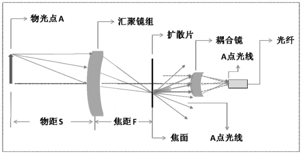
[0031] like figure 1 As shown, a high-efficiency fiber coupling system with a large field of view, the fiber coupling system includes a lens group 1, a diffuser 2 and a fiber coupling lens 3;

[0032] The lens group 1 is designed with an aspherical lens, the lens group 1 includes one or more lenses, and the lens group 1 is used to focus the light beam;

[0033] The diffuser 2 is placed at the equivalent focal plane of the lens group 1;

[0034] The material of the diffuser 2 is a polycarbonate base coating resin material;

[0035] The optical aperture of the optical fiber coupling lens 3 is equal to the diameter of the light spot produced by the lens group 1;

[0036] The fiber coupling lens 3 is placed close to the diffuser 2;

[0037] The geometric centers of lens group 1, diffuser 2 and fiber-coupled lens 3 are on the same optical axis;

[0038] The lens parameters, materials, coatings and working bands of the lens group 1 are determined by the optical design according ...


PUM


Abstract

The invention belongs to the technical field of optical lens design, and in particular relates to a high-efficiency optical fiber coupling system with a large field of view. 90%. This method can solve the problem that the existing optical fiber coupler products are limited by the numerical aperture angle of the optical fiber and the field of view is limited. The field of view, sensitivity and detection efficiency of the existing system can improve the imaging performance and have broad application prospects in the fields of quantum imaging, single-pixel imaging and computational imaging.

Description

technical field [0001] The invention belongs to the technical field of optical lens design, and in particular relates to a high-efficiency optical fiber coupling system with a large field of view. 90%. Background technique [0002] The fiber-coupled lens design technology is very mature, especially in the aspect of optical high-efficiency fiber couplers. There are mature solutions for optical fiber couplers at home and abroad, including Tholabs, Newport, Beijing Daheng Optoelectronics, Beijing Century Maofeng and other companies have shelf products. Existing fiber coupling lenses are designed for high coupling efficiency according to the numerical aperture NA of the fiber core, but the coupling field of view is small, usually the fiber NA = 0.22, and the field angle of the coupling lens that can be designed generally does not exceed 2mrad, In fact, the better the matching between the coupling lens and the NA value of the fiber, the higher the coupling efficiency, which limi...

Claims


Application Information

Patent Timeline
Patent Type & Authority Patents(China)
IPC IPC(8): G02B6/26G02B6/32
CPCG02B6/26G02B6/32
Inventor 李明飞袁梓豪何娇刘院省邓意成王学锋赵琳琳孙晓洁董鹏
Owner BEIJING INST OF AEROSPACE CONTROL DEVICES
Learn More