3D printer

A 3D printer and robotic arm technology, applied in coating devices, additive processing, etc., can solve the problems of nozzle aging, nozzle temperature rise, and high cost of construction, to increase the flow rate, ensure circulating flow, and increase spraying. effect of material

Inactive Publication Date: 2021-02-19
重庆圣盈达科技开发有限公司
View PDF0 Cites 0 Cited by
  • Summary
  • Abstract
  • Description
  • Claims
  • Application Information

AI Technical Summary

Problems solved by technology

[0003] In the 3D printing process, for 3D models with multiple different cross-sectional structures, the spraying areas of the required printing nozzles are different. If different nozzles are replaced during the printing process, firstly, frequent replacement will waste a lot of manpower and material resources. Excessive replacement time causes the sprayed material to solidify, and the subsequent spraying is still in a molten state, resulting in layering of the same layer of the model; therefore, in this field, the printing of different cross-sectional areas is often achieved by adjusting the spraying pressure and increasing the powder feeding rate.
However, by changing the process parameters to print different cross-street areas, first, the computing capacity and intelligence of the instrument are highly required (the instrument needs to store the corresponding process parameters under a large cross-sectional area, and at the same time, it needs to perform appropriate calculations to find the best matching parameters), the second is that the instrument has a high failure rate, is not easy to repair, and the later maintenance cost is high. The overall requirements for 3D printing equipment are too high, and the cost is high, which is not conducive to the promotion of 3D printing technology.
At the same time, with the progress of the 3D printing process, the temperature of the nozzle will continue to rise, and the printing material will be reheated and melted when it passes through the nozzle; this will cause serious aging of the nozzle, and even thermal breakage, and the printed model will take a long time to solidify and appear cracked. Phenomena such as layers

Method used


Image

  • 3D printer
  • 3D printer
  • 3D printer

Examples


Embodiment

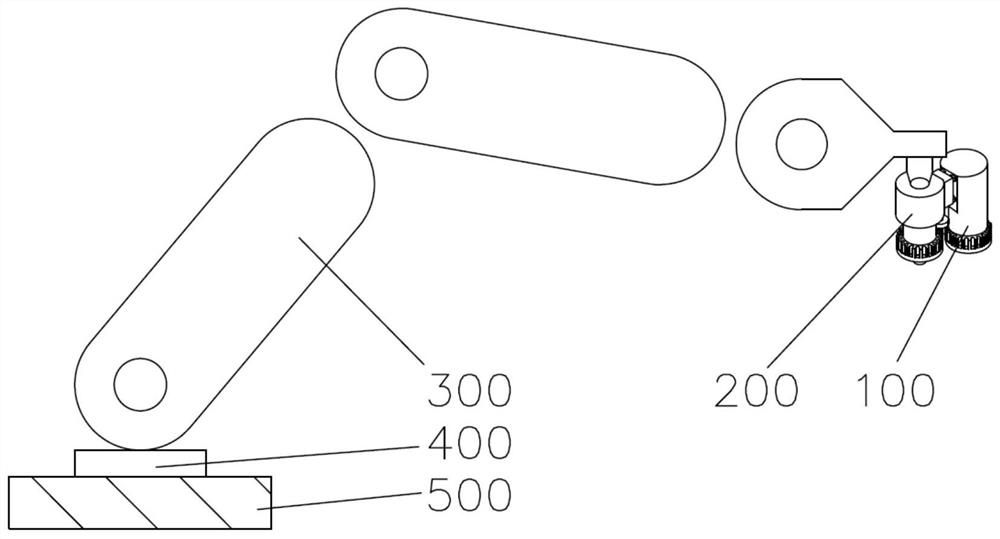
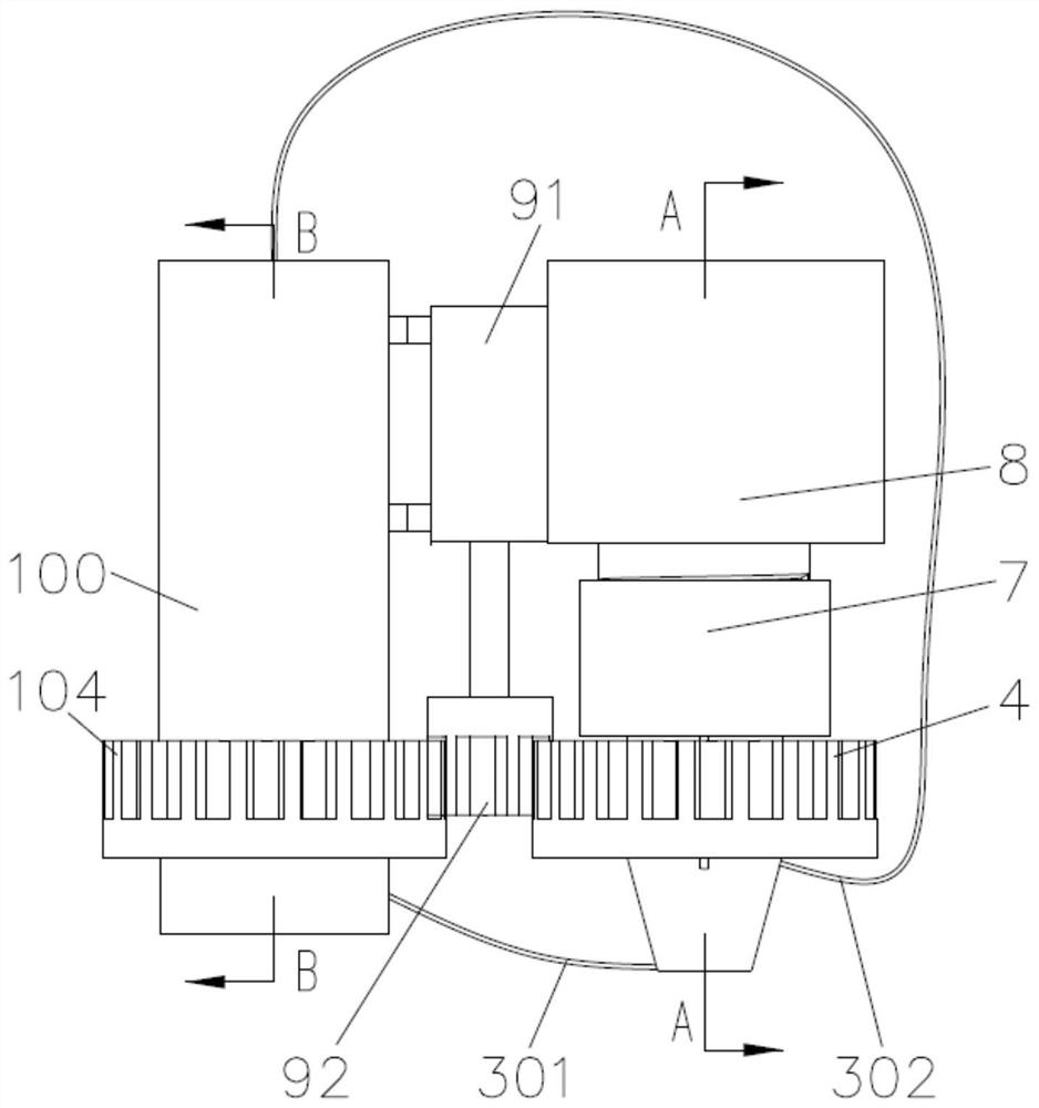
[0044] Such as Figure 1-12 As shown, a 3D printer is characterized in that it includes a fixed table 500, a rotating table 400, a mechanical arm 300, a nozzle assembly 200 and a cooling cycle assembly 100; the rotating table 400 is located above the fixed table 500 and the rotating table 400 is connected to the fixed The table 500 is rotatably connected, and one end of the robot arm 300 is fixedly connected to the side of the rotating table 400 away from the fixed table 500, and the other end clamps the nozzle assembly 200 and the cooling cycle assembly 100. The delivery channel of the 3D printing material is not connected to the robot arm 300, One end is fixedly connected to the nozzle assembly 200, and the other end is directly externally connected to the feeding device. The connection of the conveying channel of the 3D printing material is a conventional design in the prior art, and will not be elaborated in the present invention.

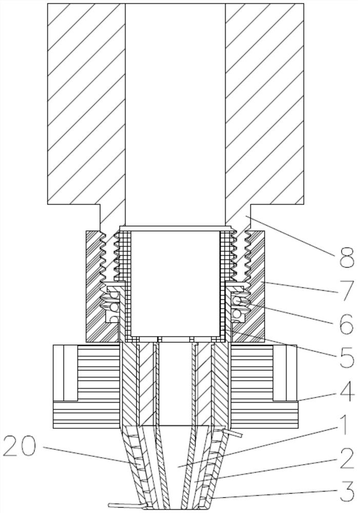
[0045] The nozzle assembly 200 includes ...


PUM


Abstract

The invention provides a 3D printer. The 3D printer comprises a fixed table (500), a rotating table (400), a mechanical arm (300), a spray head assembly (200) and a cooling circulation assembly (100),wherein the spray head assembly (200) comprises a first spray head (1), a second spray head (2), a third spray head (3), a driven gear (4), a blocking piece (5), a spring (6), a fixing piece (7), a feeding piece (8) and a driving assembly (9); and a circulating pump (101), a cooling box (102), a rotating plate (103), a gear ring (104) and a ventilation plate (105) are arranged in the cooling circulation assembly (100). According to the 3D printer, the spraying amount can be automatically adjusted according to different printing cross sectional areas, and then the area needing to be printed isadjusted so as to adapt to the overall spraying requirement; and meanwhile, the spray heads are continuously cooled in the printing process of the 3D printer, so that the phenomena that nozzles are seriously aged, and a printing model is layered are avoided.

Description

technical field [0001] The invention relates to the technical field of wheel 3D printing, in particular to a 3D printer. Background technique [0002] 3D printing, a type of rapid prototyping technology, is a technology based on digital model files, using bondable materials such as powdered metal or plastic, to construct objects by layer-by-layer printing. In the past, it was often used to make models in the fields of mold manufacturing and industrial design, and is now gradually being used in the direct manufacture of some products. In particular, some high-value applications (such as hip joints or teeth, or some aircraft parts) already have parts printed using this technology. 3D printing technology mainly heats and melts the filamentous hot-melt material, extrudes it through the printing nozzle and solidifies it; after the hot-melt material is melted, it is ejected from the nozzle and deposited on the printing table panel or the previous layer of solidified material. Cu...

Claims


Application Information

Patent Timeline
Patent Type & Authority Applications(China)
IPC IPC(8): B29C64/209B29C64/20B33Y30/00
CPCB33Y30/00B29C64/20B29C64/209
Inventor 文良均
Owner 重庆圣盈达科技开发有限公司
Why Eureka
Try Eureka