
High-resolution remote sensing image change detection network, method and device

A remote sensing image and change detection technology, applied in image enhancement, image analysis, image data processing, etc., can solve the problems of incorrect extraction of changed regions, difficulty in determining segmentation threshold, affecting the accuracy of detection results, etc. Effects of Image Features

Active Publication Date: 2021-02-12
BEIJING AEROSPACE TITAN TECH CO LTD
View PDF6 Cites 2 Cited by
  • Summary
  • Abstract
  • Description
  • Claims
  • Application Information

AI Technical Summary

Problems solved by technology

[0003] Among them, among the related change detection methods, the pixel-based change detection method is generally difficult to determine the appropriate segmentation threshold, while the object-oriented change detection method is often prone to change regions due to "same object with different spectrum, same spectrum with different objects". Mistake of
This makes the existing change detection methods generally only suitable for the ideal environment where the lighting and shooting angles of the remote sensing images corresponding to the front and back phases have small changes, less interference factors, and obvious change areas.
However, for detection in a complex environment with large changes in lighting and shooting angles, and many surrounding interference factors, it will usually cause mis-extraction of the changed area, which will affect the accuracy of the detection results.

Method used


Image

  • High-resolution remote sensing image change detection network, method and device
  • High-resolution remote sensing image change detection network, method and device
  • High-resolution remote sensing image change detection network, method and device

Examples


Embodiment Construction

[0074] Various exemplary embodiments, features, and aspects of the present disclosure will be described in detail below with reference to the accompanying drawings. The same reference numbers in the figures indicate functionally identical or similar elements. While various aspects of the embodiments are shown in drawings, the drawings are not necessarily drawn to scale unless specifically indicated.

[0075] The word "exemplary" is used exclusively herein to mean "serving as an example, embodiment, or illustration." Any embodiment described herein as "exemplary" is not necessarily to be construed as superior or better than other embodiments.

[0076] In addition, in order to better illustrate the present disclosure, numerous specific details are given in the following specific implementation manners. It will be understood by those skilled in the art that the present disclosure may be practiced without some of the specific details. In some instances, methods, means, componen...


PUM


Abstract

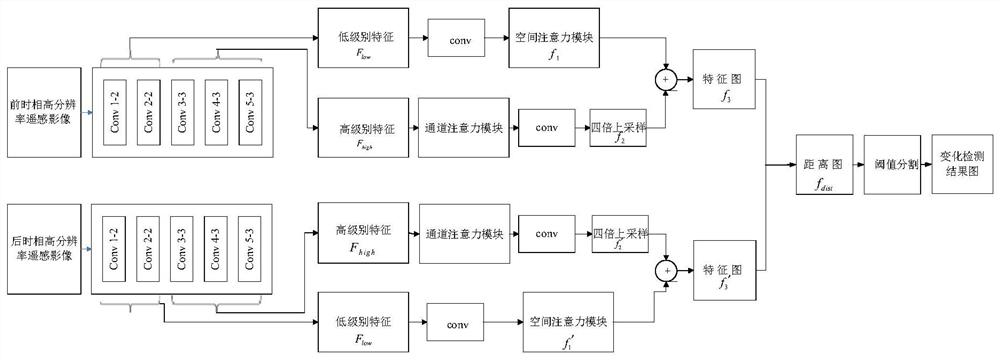
The invention relates to a high-resolution remote sensing image change detection network. The network comprises a front time phase feature extraction branch and a rear time phase feature extraction branch which are arranged in parallel; wherein the front time phase feature extraction branch comprises a first convolution module and a front time phase feature fusion module; a front time-phase feature fusion module acquires low-level front time-phase features output by a low-level convolution layer and high-level front time-phase features output by a high-level convolution layer in the first convolution module, and fuses the low-level front time-phase features and the high-level front time-phase features to obtain front time-phase feature data; the rear time phase feature extraction branch comprises a second convolution module and a rear time phase feature fusion module; and the post-time-phase feature fusion module obtains low-level post-time-phase features output by a low-level convolution layer and high-level post-time-phase features output by a high-level convolution layer in the second convolution module, and fuses the low-level post-time-phase features and the high-level post-time-phase features to obtain post-time-phase feature data. The accuracy of a detection result is effectively improved.

Description

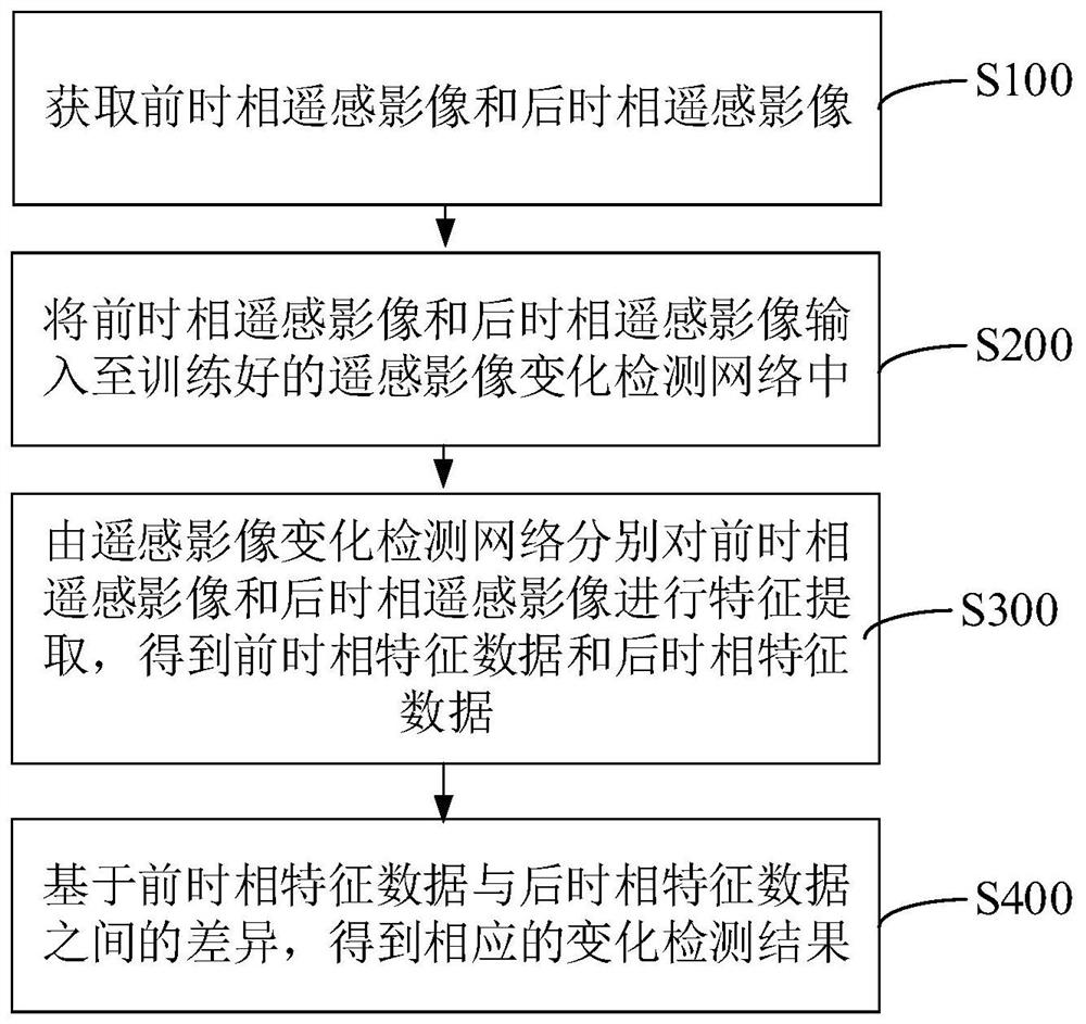
technical field [0001] The present disclosure relates to the technical field of remote sensing image processing, in particular to a high-resolution remote sensing image change detection network, method and device. Background technique [0002] Remote sensing image change detection, as one of the key technologies in the field of remote sensing technology, is playing an increasingly important role in the fields of urban planning, disaster monitoring, land resource management, and military reconnaissance. High-resolution remote sensing images have become an important data source for transform detection technology because of their high definition and strong real-time characteristics. When performing change detection based on high-resolution remote sensing images, it is often easy to produce a large number of false changes due to the influence of illumination and shooting angle, especially for some complex environments (such as: natural environments affected by seasonal image cha...

Claims


Application Information

Patent Timeline
Patent Type & Authority Applications(China)
IPC IPC(8): G06T7/246G06K9/62G06K9/00
CPCG06T7/246G06T2207/10032G06T2207/20081G06T2207/20084G06V20/13G06F18/253
Inventor 于莉楠王战举张哲任伟
Owner BEIJING AEROSPACE TITAN TECH CO LTD
Learn More