
Constructional engineering quality detector and using method thereof

A technology of construction engineering and detectors, applied in the direction of instruments, soil testing, measuring devices, etc., can solve problems such as cumbersome operation, poor prevention effect, and large labor force

Inactive Publication Date: 2021-02-12
杜文中
View PDF0 Cites 0 Cited by
  • Summary
  • Abstract
  • Description
  • Claims
  • Application Information

AI Technical Summary

Problems solved by technology

In some places, due to heavy rainwater and high water content in the soil around the foundation, when there are cracks in the foundation, they will seep into the foundation. If the inside of the foundation is soaked for a long time, it will seriously affect the mechanical strength of the foundation. The tower causes damage. When the line tower is damaged, it not only affects the normal transmission of electricity, but also causes huge economic losses to the power company, and the leaked high-voltage electricity will also cause harm to nearby people and livestock.
[0003] In the prior art, it is generally necessary for electric power technicians to detect the foundation soil under the line tower at regular intervals. Manual detection is labor-intensive, and it is necessary to insert the detector into the soil for each detection. For a certain period of time, the operation is relatively cumbersome. At the same time, this manual timing detection is difficult to prevent the occurrence of landslides in time, and the prevention effect is not good.

Method used


Image

  • Constructional engineering quality detector and using method thereof
  • Constructional engineering quality detector and using method thereof
  • Constructional engineering quality detector and using method thereof

Examples


Embodiment 1

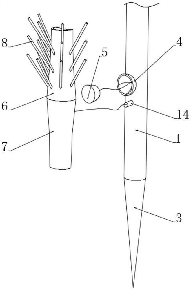
[0043] see Figure 1-2 , a construction quality pre-embedded detector, comprising a pre-embedded rod 1 and an insertion rod 3 located at the bottom of the pre-embedded rod 1, the top of the pre-embedded rod 1 is fixedly connected with a control box 2, and the side wall of the pre-embedded rod 1 There are multiple sets of soil quality detection devices embedded and installed. The soil quality detection device includes a humidity sensor 5 embedded and installed on the outer wall of the pre-embedded rod 1. The arc-shaped installation box 4, the inner end of the arc-shaped installation box 4 communicates with the inside of the embedded rod 1, the outer wall of the humidity sensor 5 is sealed and embedded with the inner wall of the arc-shaped installation box 4, and is embedded on the outer wall of the embedded rod 1. There is an infiltration coating mechanism located outside the humidity sensor 5. The infiltration coating mechanism includes an infiltration body located at the uppe...


PUM


Abstract

The invention discloses a constructional engineering quality detector and a using method thereof and belongs to the technical field of constructional engineering detection. According to the constructional engineering quality detector and the using method thereof of the invention, a plurality of soil quality detection devices are embedded at different positions on the outer side wall of a pre-buried rod so as to be used for detecting the humidity of soil at different depths. Each soil quality detection device comprises a humidity sensor embedded in the outer wall of the pre-buried rod, a permeation body wrapping the outer side of the humidity sensor and an accumulated water detection body; a relative sealing body is formed by the permeation body and the accumulated water detection body, sothat the humidity sensor is effectively isolated from the soil, and a certain anti-corrosion effect on the humidity sensor is achieved; the permeation body is used for introducing moisture in the soilinwards, so that the humidity in the soil is indirectly detected by the humidity sensor; the accumulated water detection body located at the lower end of the permeation body effectively detects the permeation amount; and when it is detected that the accumulated water amount is too large, technicians are warned to take corresponding soil reinforcement measures, and therefore, collapse phenomenon is prevented in time by means of real-time detection.

Description

technical field [0001] The invention relates to the technical field of construction engineering detection, and more specifically relates to a construction engineering quality detector and a method for using the same. Background technique [0002] At present, the construction of line poles and towers in construction projects generally pours concrete on the ground to form a foundation, and then installs steel structure poles and towers on the foundation, and the poles and towers are used for cable arrangement. In some places, due to heavy rainwater and high water content in the soil around the foundation, when there are cracks in the foundation, they will seep into the foundation. If the inside of the foundation is soaked for a long time, it will seriously affect the mechanical strength of the foundation. The tower is damaged. When the line tower is damaged, it will not only affect the normal transmission of electricity, but also cause huge economic losses to the power company...

Claims


Application Information

Patent Timeline
Patent Type & Authority Applications(China)
IPC IPC(8): G01N33/24G01F23/00
CPCG01F23/00G01N33/246
Inventor 杜文中
Owner 杜文中
Learn More