A kind of joint for carbon fiber composite arm section and preparation method thereof

A composite material and carbon fiber technology, which is applied in the processing of building materials, construction, and building construction, can solve problems such as unreasonable force conduction design, general surface quality control, and single molding method, so as to solve the problems of strength and manufacturing. The contradiction between the interface, the effect of ensuring the strength of the interface connection and good corrosion resistance

Active Publication Date: 2022-06-21
北玻院(滕州)复合材料有限公司
View PDF6 Cites 0 Cited by
  • Summary
  • Abstract
  • Description
  • Claims
  • Application Information

AI Technical Summary

Problems solved by technology

In this technology, the metal shafts bearing the force at the end are processed in series and the outer ring is reinforced with carbon cloth, and embedded in the foam material, because the corresponding shaft hole embedded in the foam material is only supported by the composite material shell on both sides. Positioning and connection constraints are unreasonable in the design of force transmission, and there are hidden dangers of fatigue damage at the position of the shaft hole for long-term use
[0004] Therefore, the existing composite boom joints have problems of insufficient strength, single forming method, high cost, or general surface quality control

Method used


Image

  • A kind of joint for carbon fiber composite arm section and preparation method thereof
  • A kind of joint for carbon fiber composite arm section and preparation method thereof
  • A kind of joint for carbon fiber composite arm section and preparation method thereof

Examples


Embodiment 1

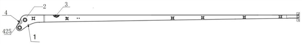
[0047] like figure 1 As shown, it is a carbon fiber composite material arm section, and the large end of the carbon fiber composite material arm section is a joint 1 for a carbon fiber composite material arm section in this embodiment, including: a carbon fiber composite material joint shell 2, a joint inner core 3 , The end is connected to the embedded part 4. The joint inner core 3 is filled in the interior of the carbon fiber composite material joint shell 2; the end connection embedded parts 4 are arranged at the end of the carbon fiber composite material joint shell 2 and embedded in the joint inner core for The connection between the big end of a carbon fiber composite boom section and another boom section or hydraulic device.

[0048] When the joint for the carbon fiber composite arm section of this embodiment is used, the big end of the arm section is connected to the small end of the previous arm section through the end connecting embedded part 4 of the joint. The c...

Embodiment 2

[0069] In the preparation method of the joint for carbon fiber composite material arm section described in this embodiment, the preparation steps and the size of the arm section are the same as those in Embodiment 1, the difference is that the autoclave forming process is used for forming in step S4, and the forming process is adopted in step S5. Resin transfer molding process or RTM process for molding.


PUM


Abstract

The invention provides a carbon fiber composite material arm joint joint and a preparation method thereof, comprising: a carbon fiber composite material joint shell; a joint inner core filled in the carbon fiber composite material joint shell; The end part pre-embedded in the carbon fiber composite material joint shell is embedded in the joint inner core, and is used for connecting the end part of the carbon fiber composite material arm section. The joint for the carbon fiber composite boom section adopts a hollowed-out overall metal frame composite material covering and pre-embedded form, taking into account the weight and interface connection strength; the inner core of the joint is pierced with a three-dimensional grid-like reinforcement to strengthen the shell of the jib joint The internal pulling; the joint shell is prepared by using different molding processes to compound, which can achieve relatively small mass and cost to obtain high structural efficiency.

Description

technical field [0001] The invention belongs to the technical field of concrete pump trucks, and in particular relates to a carbon fiber composite material arm section joint and a preparation method thereof. Background technique [0002] Concrete pump trucks play an irreplaceable role in many fields of modern construction. With the development of the modern construction field, the requirements for the height of the boom of the concrete pump truck are getting higher and higher, so the development trend of the boom of the concrete pump truck being longer and higher becomes inevitable. The boom of the traditional concrete pump truck is made of high-strength alloy steel, and the weight increases with the increase of the deployment height, which puts forward higher requirements for the stowage and safety performance of the concrete pump truck, and for the construction scheduling and work site of the pump truck produce great limitations. High-strength alloy steel has certain hid...

Claims


Application Information

Patent Timeline
Patent Type & Authority Patents(China)
IPC IPC(8): E04G21/04B29C70/68
CPCE04G21/04E04G21/0445B29C70/68B29C70/681
Inventor 张为军刘辉黄其忠李瑞盈毛雅赛李义全尹双双丁庆强陈锋陈万康毛义梅
Owner 北玻院(滕州)复合材料有限公司
Why Eureka
Try Eureka