A clamping device for carbon electrode extruder

A carbon electrode and clamping device technology, which is applied in the direction of presses, material forming presses, friction clamped detachable fasteners, etc., can solve the problem of frequent opening and closing of clamping rings, low production efficiency, and problems with clamping rings. Short service life and other problems, achieve the effect of stable and reliable clamping and disengagement process, improve production efficiency and service life

Active Publication Date: 2022-03-29
DALIAN DESIGN INST CO LTD CHINA FIRST HEAVY IND +1
View PDF6 Cites 0 Cited by
  • Summary
  • Abstract
  • Description
  • Claims
  • Application Information

AI Technical Summary

Problems solved by technology

This connection method exists: the bolts and nuts need to be disassembled to replace the spout, and because the material chamber and the spout are deformed by heat, it is difficult to disassemble, and it is necessary to use multiple auxiliary piston cylinders to work at the same time to open the clamping ring and realize the detachment of the spout and the material chamber; Due to the frequent opening and closing of the clamping ring, the life of the clamping ring is short
In order to solve this problem, in the prior art, there is a patented technology with the application number CN201410130671.X and the name "Nozzle Snap Ring and Carbon Extruder". This technology can realize the opening and closing of the clamping ring, but The adjustment of the clamping force of the nozzle and the rapid replacement of the nozzle cannot be realized; the production efficiency is low, the production line cannot be seamlessly connected, and the whole line cannot be automated

Method used


Image

  • A clamping device for carbon electrode extruder
  • A clamping device for carbon electrode extruder
  • A clamping device for carbon electrode extruder

Examples


Embodiment Construction

[0022] The present invention will be further described below in conjunction with the accompanying drawings and specific embodiments.

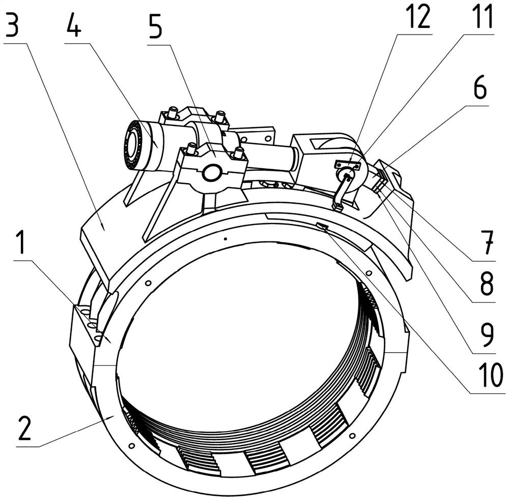
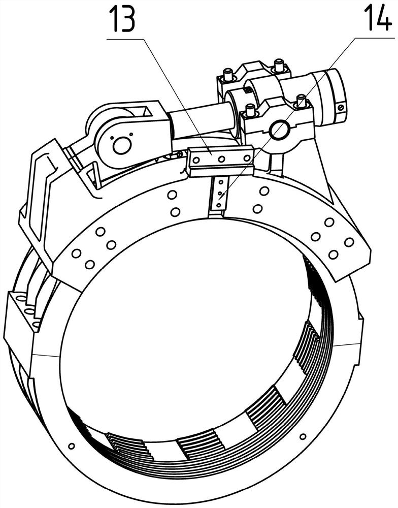
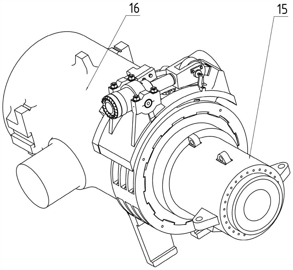
[0023]Clamping device for carbon electrode extruder, including clamping ring and hydraulic clamping mechanism connecting carbon electrode extruder material chamber 16 and mouth 15, clamping ring includes clamping upper ring 1 and clamping lower ring Ring 2, clamping upper ring 1 and clamping lower ring 2 are connected by bolts, and the outer surface of clamping upper ring 1 is provided with positioning grooves. The hydraulic clamping mechanism includes bracket 3, hydraulic clamping cylinder 4, penguin plate 6, pad The block group and the positioning key; the bracket 3 includes an arc bottom plate, a bearing frame and a tail block. The arc plate is an arc plate that matches the outer circle of the clamping upper ring 1. There is a long slot hole in the middle of the arc plate. The side of the arc plate on the side connected to the material chamb...


PUM


Abstract

A clamping device for a carbon electrode extruder, including a clamping ring and a hydraulic clamping mechanism connecting the material chamber of the carbon electrode extruder with a nozzle, the clamping ring is composed of a clamping upper ring and a clamping lower ring The hydraulic clamping mechanism includes a bracket, a hydraulic clamping cylinder, a penguin plate and a gasket block group; the bracket is connected with the material chamber of the carbon electrode extruder through bolts, and the base of the penguin plate is connected with the clamping upper ring through bolts , the top of the penguin plate is connected with the hydraulic clamping cylinder, the inner surface of the clamping ring connected with the material chamber of the carbon electrode extruder is processed with an annular trapezoidal groove, and the outer surface of the material chamber is processed with the same annular trapezoidal groove; the clamping ring on the side connected with the mouth The inner surface of the ring is processed with slotted zigzag threads, several grooves are evenly distributed along the inner circumference of the clamping ring, and the outer surface of the mouth is processed with the same zigzag threads. The beneficial effect is that the replacement of the nozzle is convenient, the time is short, the production efficiency is high, and the service life is long. The clamping and unclamping process is smooth and reliable. Can withstand large axial force.

Description

technical field [0001] The invention belongs to the technical field of forging equipment, in particular to a clamping device for a carbon electrode extrusion machine. Background technique [0002] In the prior art, the connection between the material chamber and the nozzle of the carbon electrode extruder is usually connected by a clamping ring formed by two semicircular flanges. This connection method exists: the bolts and nuts need to be disassembled to replace the spout, and because the material chamber and the spout are deformed by heat, it is difficult to disassemble, and it is necessary to use multiple auxiliary piston cylinders to work at the same time to open the clamping ring and realize the detachment of the spout and the material chamber; Due to the frequent opening and closing of the clamping ring, the life of the clamping ring is short. In order to solve this problem, in the prior art, there is a patented technology with the application number CN201410130671.X ...

Claims


Application Information

Patent Timeline
Patent Type & Authority Patents(China)
IPC IPC(8): B30B11/22B30B15/02F16B2/20
CPCB30B11/22B30B11/221B30B15/026F16B2/20
Inventor 唐志超郝铁文王文婷殷文齐
Owner DALIAN DESIGN INST CO LTD CHINA FIRST HEAVY IND
Why Eureka
Try Eureka