Equipment used for carrying out punching on textile cloth

A technology of textile cloth and equipment, which is applied in the field of equipment for punching textile cloth, can solve the problems of cloth tearing, unqualified holes, and inability to use drilling, etc., and achieve the effect of increasing punching quality and improving efficiency

Inactive Publication Date: 2021-02-12
淮安聚友新能源科技有限公司
View PDF11 Cites 0 Cited by
  • Summary
  • Abstract
  • Description
  • Claims
  • Application Information

AI Technical Summary

Problems solved by technology

[0002] Textile cloth is a cloth made of cotton thread, yarn, silk or other materials after weaving, and some cloth needs to be provided with holes when it is used, so it is necessary to punch holes in the Dudi cloth in advance, because the cloth is flammable, so it cannot be used The way of drilling can only be punched by punching. In the traditional punching process, the feeding roller and the receiving roller are placed on both sides of the punching equipment, and then the cloth is punched Through the equipment, the punching method is used to punch holes during the conveying process of the cloth. However, it often happens that the lifting speed of the punching head in the punching equipment does not match the conveying speed of the cloth, resulting in tearing of the cloth. The problems of cracking and unqualified holes seriously affect the quality and processing efficiency of the fabric

Method used


Image

  • Equipment used for carrying out punching on textile cloth
  • Equipment used for carrying out punching on textile cloth
  • Equipment used for carrying out punching on textile cloth

Examples


Embodiment Construction

[0023] The technical solutions in the embodiments of the present invention will be clearly and completely described below in conjunction with the accompanying drawings in the embodiments of the present invention. Obviously, the described embodiments are only some of the embodiments of the present invention, not all of them. Based on The embodiments of the present invention and all other embodiments obtained by persons of ordinary skill in the art without making creative efforts belong to the protection scope of the present invention.

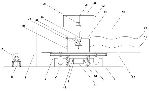
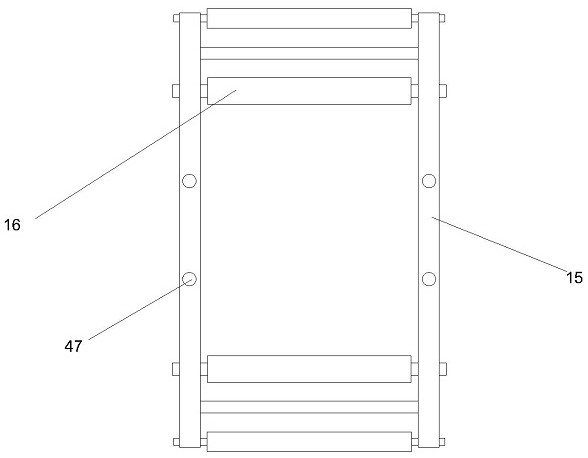
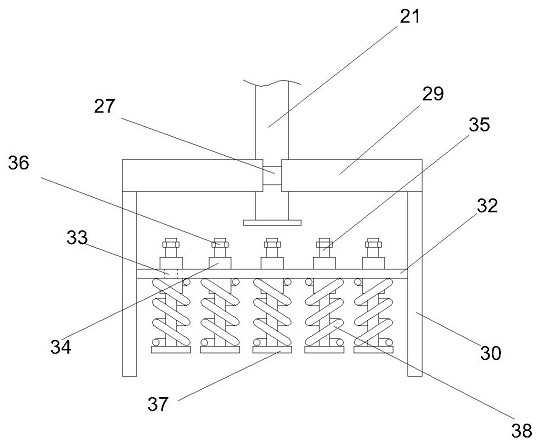
[0024] refer to Figures 1 to 7 As shown, a kind of equipment for punching woven fabrics includes a base plate 1, a transmission part 2 and an upper punching part, the base plate 1 is provided with a supporting platform 3, and the supporting platform 3 is provided with There is a middle groove 4 and a side groove 5, the length of the middle groove 4 and the side groove 5 are the same as the width of the support platform 3, a bracket 6 is arrange...


PUM


Abstract

The invention discloses equipment used for carrying out punching on textile cloth. The equipment comprises a base plate, a conveying part and an upper punching part, and is structurally characterizedin that a bearing table is arranged on the base plate, a middle groove and a side edge groove are formed in the bearing table, the length of the middle groove and the length of the side edge groove are the same as the width of the bearing table, a support is arranged on one side of the base plate, a material receiving roller is connect to the support in a coupled mode, an upper gear is arranged atthe tail end of a center shaft of the material receiving roller, and a brake motor is connected to the support through a spring. The equipment used for carrying out punching on the textile cloth hasthe beneficial effects that when punching is carried out on the cloth, the lower end of a pressing rod moves downwards through extension of an electric telescopic rod and then pushes a horizontal plate downwards, so that a conveying roller is separated from the surface of the cloth; meanwhile, the brake motor is separated from a material receiving roller, at the moment, the cloth loses conveying force, and therefore punching can be carried out on the cloth under the condition that the cloth does not move.

Description

technical field [0001] The invention belongs to the field of textile equipment, and in particular relates to a device for punching holes in textile cloth. Background technique [0002] Textile cloth is a cloth made of cotton thread, yarn, silk or other materials after weaving, and some cloth needs to be provided with holes when it is used, so it is necessary to punch holes in the Dudi cloth in advance, because the cloth is flammable, so it cannot be used The way of drilling can only be punched by punching. In the traditional punching process, the feeding roller and the receiving roller are placed on both sides of the punching equipment, and then the cloth is punched Through the equipment, the punching method is used to punch holes during the conveying process of the cloth. However, it often happens that the lifting speed of the punching head in the punching equipment does not match the conveying speed of the cloth, resulting in tearing of the cloth. The problems of cracking...

Claims


Application Information

Patent Timeline
IPC IPC(8): B26F1/14B26D5/08B26D7/06B26D7/02
CPCB26F1/14B26D5/086B26D7/06B26D7/025B26F2210/12
Inventor 孙英
Owner 淮安聚友新能源科技有限公司
Why Eureka
Try Eureka