Precise small hole stamping mold of filtering plate

A technology for punching small holes and filter plates, applied in the field of punching dies and filter plates accurately punching small hole dies, can solve the problems of difficult operation, reduced production efficiency, short service life, etc. Effect

Inactive Publication Date: 2015-11-25
DALIAN YILIAN METAL FORMING
View PDF6 Cites 0 Cited by
  • Summary
  • Abstract
  • Description
  • Claims
  • Application Information

AI Technical Summary

Problems solved by technology

[0002] In the prior art, the structure of the filter plate punching small hole die is complex, the service life is short, the operation is difficult during use, and it cannot be positioned accurately, so the labor intensity is increased, the production efficiency is reduced, and the product quality is greatly affected; Chinese application number 201210224132.3, Disclosed is a small hole punching die for a partition, comprising an upper template, a backing plate, a punch fixing plate, a rubber, a die, a lower template, a stripping plate, a punch, a first guide post, a second guide post and a guide sleeve , the backing plate is installed on the lower end of the upper formwork, the punch fixing plate is installed on the lower end of the backing plate, the die is installed on the lower formwork, the stripping plate is installed on the die, the rubber, the punch and the first guide post are respectively installed on the punch and fixed Between the plate and the stripper plate, the second guide post is installed between the upper formwork and the lower formwork, and the guide sleeve is installed on the upper end of the second guide post

Method used


Image

  • Precise small hole stamping mold of filtering plate
  • Precise small hole stamping mold of filtering plate

Examples


Embodiment Construction

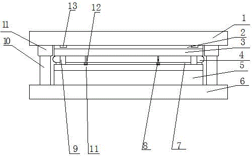
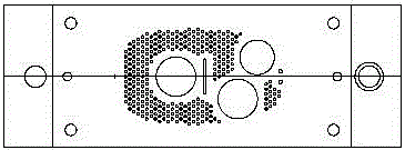
[0013] Such as figure 1 and figure 2 The precision punching small hole die for the filter plate shown includes an upper template 1 and a lower template 6, a guide sleeve 11 and an outer guide post 10 arranged between the upper template and the lower template, and a backing plate 2 arranged on the bottom surface of the upper template , and the punch fixing plate 3 arranged below the backing plate, and the unloading plate 7 connected to the lower punch fixing plate through the inner guide column 9, and the punch 8 arranged on the punch fixing plate, and the punch 8 arranged on the lower The die 5 on the template and the rubber 4 arranged between the punch fixing plate and the die are provided with a frame-shaped positioning frame 14 on the periphery of the discharge plate; the frame-shaped positioning frame 14 is movable through the guide column 9 and installed To the rear punch fixing plate 12; the discharge plate 7 is provided with a punch guide cylinder 12 movable around th...


PUM


Abstract

The invention discloses a precise small hole stamping mold of a filtering plate. The precise small hole stamping mold comprises an upper mold plate, a lower mold plate, guide sleeves, outer guide columns, a cushion plate arranged on the bottom face of the upper mold plate, a punch fixing plate arranged below the cushion plate, a stripper plate connected to the portion below the punch fixing plate through inner guide columns, a punch arranged on the punch fixing plate, a female mold arranged on the lower mold plate and a rubber arranged between the punch fixing plate and the female mold, wherein the guide sleeves and the outer guide columns are arranged between the upper mold plate and the lower mold plate. A frame-shaped positioning frame is arranged on the periphery of the stripper plate. The frame-shaped positioning frame movably penetrates and is installed on the punch fixing plate on the rear side through the guide columns. A punch guiding barrel is movably arranged on the part, on the periphery of the punch, of the stripper plate. According to the precise small hole stamping mold of the filtering plate, positioning is carried out in advance through the frame-shaped positioning frame, material pressing is carried out on the periphery of the filtering plate, and then the punch carries out rapid impact along the punch guiding barrel. The precise small hole stamping mold is precise in positioning and high in punching quality.

Description

technical field [0001] The invention relates to a punching die, in particular to a die for precisely punching small holes in a filter plate, and belongs to the technical field of dies. Background technique [0002] In the prior art, the structure of the filter plate punching small hole die is complex, the service life is short, the operation is difficult during use, and it cannot be positioned accurately, so the labor intensity is increased, the production efficiency is reduced, and the product quality is greatly affected; Chinese application number 201210224132.3, Disclosed is a small hole punching die for a partition, comprising an upper template, a backing plate, a punch fixing plate, a rubber, a die, a lower template, a stripping plate, a punch, a first guide post, a second guide post and a guide sleeve , the backing plate is installed on the lower end of the upper formwork, the punch fixing plate is installed on the lower end of the backing plate, the die is installed o...

Claims


Application Information

Patent Timeline
IPC IPC(8): B21D28/34B21D43/00
Inventor 白林范久卫孙冬生
Owner DALIAN YILIAN METAL FORMING
Why Eureka
Try Eureka