High-security cam lock mounting equipment

A technology for installing equipment and cam locks, which is applied in metal processing equipment, drilling/drilling equipment, feeding devices, etc., can solve the problem that the center of the front hole and the rear hole cannot be guaranteed to be on the same horizontal line, the stability cannot be guaranteed, and the In the event of drilling deviation and other problems, the effect of improving the drilling quality, reducing the degree of artificial influence, and avoiding drilling errors

Active Publication Date: 2020-09-04
宁波韦迩五金工贸有限公司
View PDF8 Cites 0 Cited by
  • Summary
  • Abstract
  • Description
  • Claims
  • Application Information

AI Technical Summary

Problems solved by technology

[0003] The general installation method of the rotary cam lock is as follows: firstly, determine the center of the lock body and the lock tongue according to the fixed distance template; Dig the socket of the lock tongue; then remove the handle on one side with a tool, put the lock tongue into the lock tongue hole on the side of the door, fix it with screws, install the lock body, insert the lock body hole indoors, and buckle the lock at the same time At the tail end of the tongue, after ensuring that the lock body and the lock tongue are integrated, adjust the position of the outer adjustment ring so that the center of the lock body is at the center of the door lock, and put the temporal handle on the handle tube, and press it with the closed end of the accessory. Lower the positioning card, and then push it into the inner handle, so that the two can be pinned to complete the installation; among them, drilling is the basis for the installation of the rotary cam lock, and the quality of the drilling directly determines the use effect of the rotary cam lock after installation. In the prior art, people usually use manual hand-held drilling, but because there is no limit device in this drilling method, drilling deviation is prone to occur during the drilling process, and the center of the front hole and the rear hole cannot be guaranteed to be on the same horizontal line; The installation of the rotary cam lock is sometimes installed in a centralized manner in the factory area, which creates a large workload. The manual drilling of the installation master will cause a large resource consumption in the later stage of the work, and the stability cannot be guaranteed.

Method used


Image

  • High-security cam lock mounting equipment
  • High-security cam lock mounting equipment
  • High-security cam lock mounting equipment

Examples


Embodiment Construction

[0025] The technical solutions in the embodiments of the present invention will be clearly and completely described below in conjunction with the accompanying drawings in the embodiments of the present invention. Obviously, the described embodiments are only a part of the embodiments of the present invention, rather than all the embodiments. Based on the embodiments of the present invention, all other embodiments obtained by those of ordinary skill in the art without creative work shall fall within the protection scope of the present invention.

[0026] In the description of the invention, it should be noted that the terms "upper", "lower", "inner", "outer", "front end", "rear end", "both ends", "one end", "other end", etc. The indicated orientation or positional relationship is based on the orientation or positional relationship shown in the drawings, which is only for the convenience of describing the present invention and simplifying the description, rather than indicating or i...


PUM


Abstract

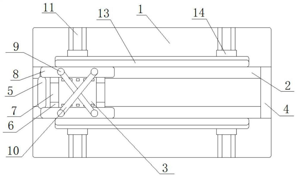
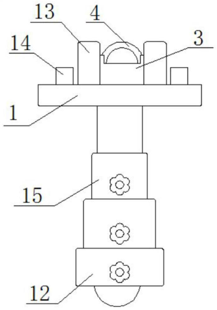
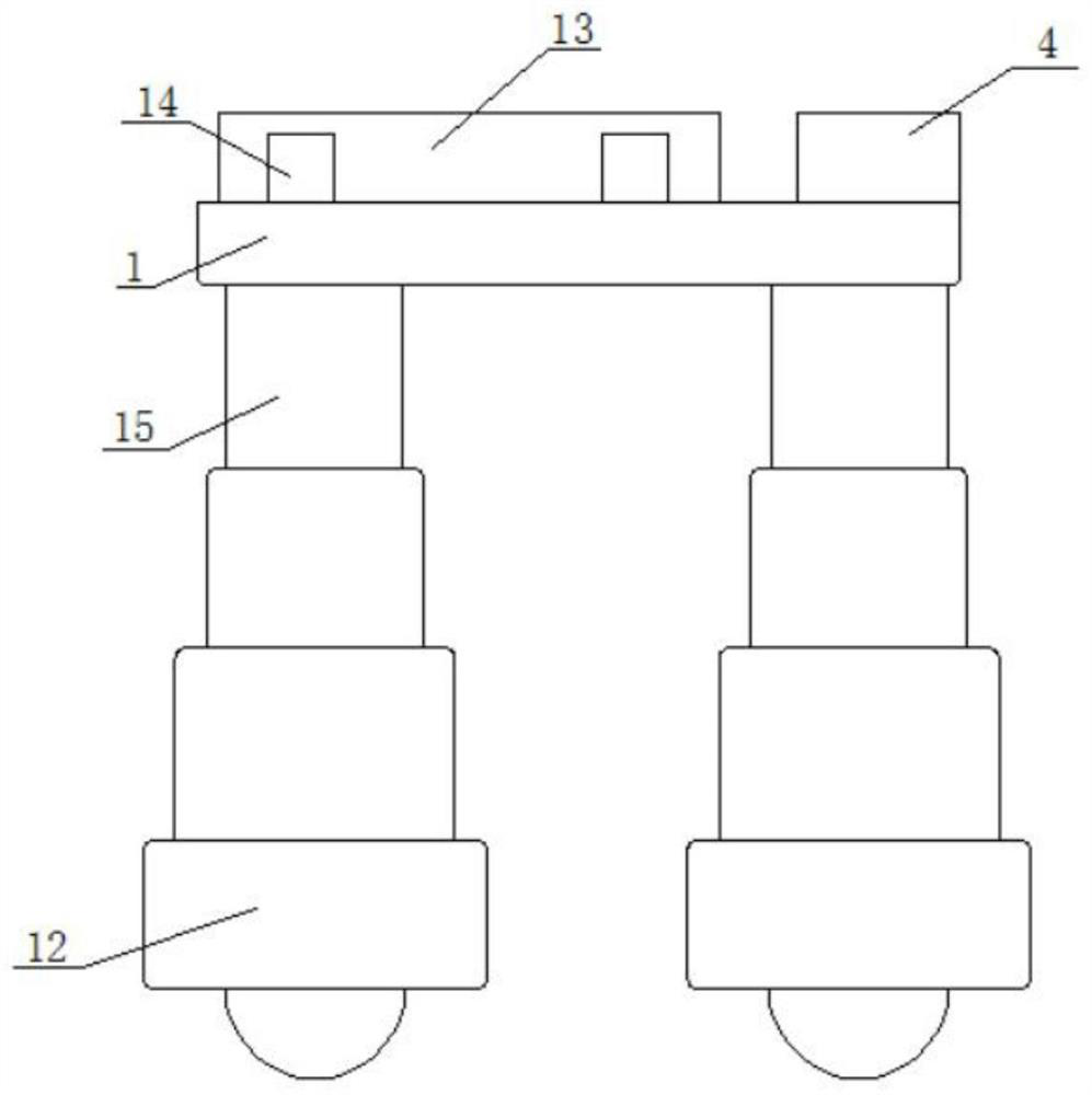
The invention discloses high-security cam lock mounting equipment which comprises a platform, wherein a bottom table is connected with the bottom end of the platform through a telescopic rod; a sliding chute is arranged on the upper surface of the platform; an object carrying table is arranged at one end of the sliding chute; a shock-absorbing ring is mounted at the other end of the sliding chute;a handle is arranged on one end of the object carrying table; side plates are symmetrically arranged on the upper surface of the object carrying table; grooves are formed in the surfaces of the sideplates; clamping plates are arranged by the side of the side plates; the lower surfaces of the clamping plates get in touch with the upper surface of the object carrying table; wire fastening nails are symmetrically arranged on the surfaces of the clamping plates in a buckling manner; and fixing wires are wound around the surfaces of the wire fastening nails. Through the arrangement of a shock-absorbing belt, the grooves, the wire fastening nails and the sliding chute as well as through the replacement of an original manual structure with a simple structure, the working effects of low-cost investment and high-efficiency return are achieved; and through the combination between the high-security cam lock mounting equipment and human power, the steady positioning effect can be achieved, the punching accuracy and stability of the high-security cam lock mounting equipment can be improved, and the whole experience about the mounting of a cam lock can be improved.

Description

Technical field [0001] The invention relates to the technical field of cam lock installation equipment, in particular to a high security cam lock installation equipment. Background technique [0002] The cam lock, the English name CAM LOCK, literally translates to cam. The cam lock is widely used. The cam lock body is composed of a lock and a cylinder. The common cam locks mainly include a plum marble lock, a blade cam lock, Triangular cam locks, double-sided marble cam locks and anti-theft cam lock mailbox locks. The plum marble lock refers to the internal structure that controls the transmission of the lock nail is a copper pin. It is small in size and can be used for two hundred keys. The largest size It can contain seven copper marbles, can do tens of thousands of keys, and has high security performance. It is currently the most used type of lock in industry and commerce. The blade cam lock refers to the internal structure of the lock nail that controls the rotation of the lo...

Claims


Application Information

Patent Timeline
Patent Type & Authority Applications(China)
IPC IPC(8): B23B41/00B23B47/00B23B47/18
CPCB23B41/00B23B47/00B23Q5/22
Inventor 蒋琦杰
Owner 宁波韦迩五金工贸有限公司
Why Eureka
Try Eureka