Automatic detection device for tool wear

An automatic detection device and tool wear technology, which is applied in the direction of manufacturing tools, measuring/indicating equipment, metal processing machinery parts, etc., can solve the problems of high work intensity, low efficiency, and inability to detect tool wear in real time, so as to reduce work Strength, accurate detection of tool wear, and the effect of improving detection accuracy

Pending Publication Date: 2021-02-12
GUANGDONG HONGTEO ACCURATE TECH (TAISHAN) CO LTD
View PDF0 Cites 0 Cited by
  • Summary
  • Abstract
  • Description
  • Claims
  • Application Information

AI Technical Summary

Problems solved by technology

[0005] The efficiency of the existing tool measurement method is not high, and the staff need to manually remove the worn tool at all times, the work intensity is high, and it is impossible to detect the wear amount of the tool in the X, Y, and Z directions in real time

Method used


Image

  • Automatic detection device for tool wear
  • Automatic detection device for tool wear
  • Automatic detection device for tool wear

Examples


Embodiment Construction

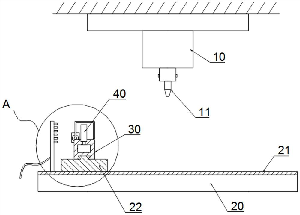
[0036] see Figure 1 to Figure 3 , a tool wear automatic detection device of the present embodiment, comprising a headstock 10, a working platform 20, a detection platform 30, a detection assembly 40, a compensation assembly and an air blowing assembly;

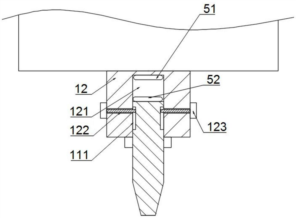
[0037] Specifically, the output end of the spindle box 10 is connected with a tool 11, the spindle box 10 can drive the tool 11 to move in X, Y, and Z directions, and the spindle box 10 can also drive the tool 11 to rotate;

[0038] Specifically, the working platform 20 is arranged below the headstock 10;

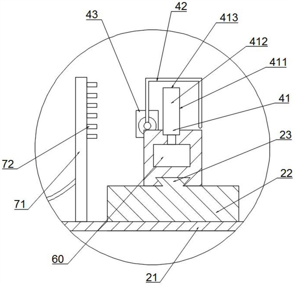
[0039] Specifically, the detection platform 30 is arranged on the work platform 20, and the detection platform 30 can move along the X direction and the Y direction on the work platform 20; to realize the movement of the detection platform 30 on the work platform 20, conventional technical means can be selected Realize, do not go into details again, preferably, X track 21 is set on described working platform 20, Y platfor...


PUM


Abstract

The invention relates to an automatic detection device for tool wear. The automatic detection device comprises a spindle box, a working platform and a detection assembly. The output end of the spindlebox is connected with a tool, and the spindle box can drive a tool to move in the X, Y and Z directions and can also drive the tool to rotate. The working platform is arranged below the spindle box.The detection assembly is used for measuring the position of the tool in the X, Y and Z directions. The detection assembly comprises a tool setting sensor. The tool setting sensor comprises an X-direction tool setting face, a Y-direction tool setting face and a Z-direction tool setting face. According to the automatic detection device, the spindle box drives the tool to make contact with the X-direction tool setting face, the Y-direction tool setting face and the Z-direction tool setting face of the tool setting sensor, the displacement difference of the spindle box in the X, Y and Z directions during initial tool setting and actual detection is calculated, and then the tool wear amount is obtained; and a machining center detects the tool in real time according to the tool wear amount, detection can be conducted without dismounting the tool, the detection efficiency and detection precision are greatly improved, and the work intensity of workers is relieved.

Description

technical field [0001] The invention relates to the technical field of tool detection equipment, in particular to an automatic detection device for tool wear. Background technique [0002] Tool wear is a common phenomenon in mechanical processing. After the tool is worn, the machining accuracy of the workpiece is reduced, the surface roughness is increased, and the cutting force is increased, the cutting temperature is increased, and even vibration is generated, and normal cutting cannot continue . Therefore, tool wear directly affects machining efficiency, quality and cost. The existing wear degree detection assembly can only detect one tool at a time. When detecting the next one, the front one needs to be removed and placed to clamp the next one. The operation is complicated, the workload is heavy, and the efficiency is low. [0003] Therefore, tool failure in the form of tool life, wear, and tool breakage has an increasingly significant impact on the working state of th...

Claims


Application Information

Patent Timeline
IPC IPC(8): B23Q17/09
CPCB23Q17/09B23Q17/0957
Inventor 苏华安李志坚邓桂绍
Owner GUANGDONG HONGTEO ACCURATE TECH (TAISHAN) CO LTD
Why Eureka
Try Eureka