
CNC-based machined part cooling device

A technology of cooling device and workpiece, applied in metal processing mechanical parts, positioning device, metal processing equipment and other directions, can solve the problems of reducing the practicability of digital control machine tools, affecting the surface hardness of the workpiece, affecting the machining accuracy, etc., to reduce the temperature , The effect of reducing scrap rate and improving production efficiency

Inactive Publication Date: 2021-02-12
苏州特莱富精密机械有限公司
View PDF5 Cites 2 Cited by
  • Summary
  • Abstract
  • Description
  • Claims
  • Application Information

AI Technical Summary

Problems solved by technology

[0003] During the processing of the existing digital control machine tool, the rapid friction between the high-speed rotating processing rod and the workpiece will generate a lot of heat. The long-term high temperature will affect the surface hardness of the workpiece, affect the processing accuracy, and the scrap rate is high, resulting in Reduced utility of existing numerically controlled machine tools

Method used


Image

  • CNC-based machined part cooling device
  • CNC-based machined part cooling device
  • CNC-based machined part cooling device

Examples


Embodiment Construction

[0019] In order to explain the overall concept of the present invention more clearly, the following will be described in detail by way of examples in conjunction with the accompanying drawings.

[0020] In describing the present invention, it is to be understood that the terms "center", "upper", "lower", "front", "rear", "left", "right", "vertical", "horizontal", The orientation or positional relationship indicated by "top", "bottom", "inner", "outer", "axial", "radial" and "circumferential" are based on the orientation or positional relationship shown in the drawings, only It is for the convenience of describing the present invention and simplifying the description, but does not indicate or imply that the referred device or element must have a specific orientation, be constructed and operated in a specific orientation, and thus should not be construed as limiting the present invention.

[0021] In addition, the terms "first" and "second" are used for descriptive purposes only...


PUM


Abstract

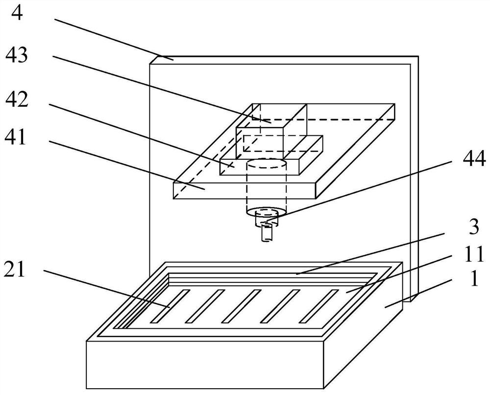
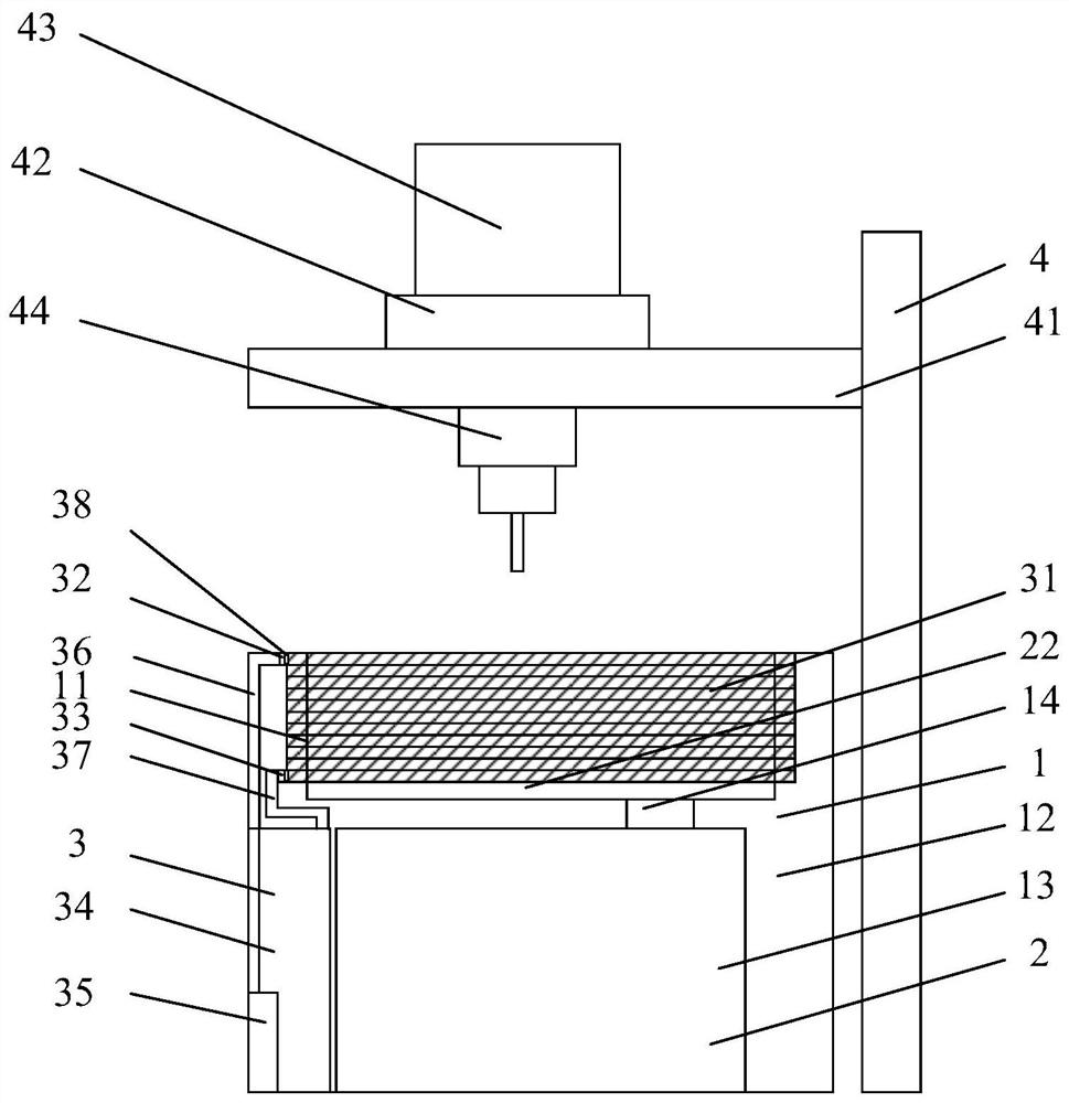
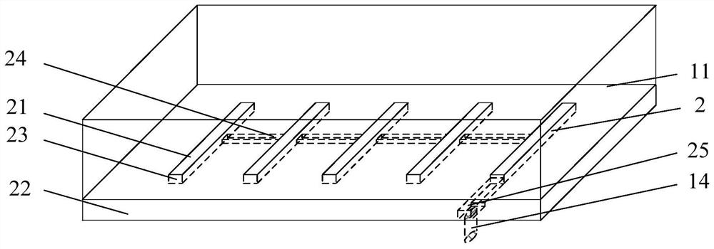
The invention discloses a CNC-based machined part cooling device. The device comprises a workbench for allowing a machined part to be fixed, a groove matched with the machined part is formed in the upper end face of the workbench, the bottom of the groove is connected with a vacuum mechanism, and a cooling mechanism is wound on the side wall, located in the workbench, of the groove. A side plate is vertically arranged on any side of the workbench, a fixed plate is horizontally arranged on the side, facing the workbench, of the side plate, a rotating motor and a hydraulic air cylinder are arranged on the upper end face of the fixed plate, the rotating motor and the hydraulic air cylinder are connected with a machined rod part, and the machined rod part is located over the groove. Accordingto the CNC-based machined part cooling device, the to-be-machined part is embedded in the matched groove, vacuum adsorption fixing is completed through groove channels communicating with a vacuum pump, meanwhile, a circulating water pipe wound around the side wall, located in the workbench, of the groove can supply cooling liquid through a circulating water pump, the temperature of the machined part is reduced, the surface hardness of the machined part is ensured, the rejection rate is reduced, and the production efficiency is improved.

Description

technical field [0001] The invention belongs to the technical field of numerical control machine tool processing, and in particular relates to a cooling device for workpieces based on CNC. Background technique [0002] CNC is the abbreviation of numerical control machine tool, which is a commonly used processing equipment for processing complex, precise and multi-standard metal parts; [0003] During the processing of the existing digital control machine tool, the rapid friction between the high-speed rotating processing rod and the workpiece will generate a lot of heat. The long-term high temperature will affect the surface hardness of the workpiece, affect the processing accuracy, and the scrap rate is high, resulting in Existing numerically controlled machine tools are less practical. Therefore, a solution is needed to solve the above problems. [0004] It should be noted that the above content belongs to the scope of the inventor's technical cognition and does not nece...

Claims


Application Information

Patent Timeline
Patent Type & Authority Applications(China)
IPC IPC(8): B23Q11/10B23Q3/08
CPCB23Q3/088B23Q11/10
Inventor 陈龙飞
Owner 苏州特莱富精密机械有限公司
Learn More