Debris cleaning device for numerical control machine tool

A cleaning device, a technology of CNC machine tools, applied in metal processing machinery parts, maintenance and safety accessories, metal processing equipment, etc., can solve the problems of affecting the machine tool, reducing the cleaning effect of debris, inability to coexist and linkage, etc., to achieve smooth operation, Easy to clean and easy to discharge

Inactive Publication Date: 2021-02-12
XINXIANG VOCATIONAL & TECHN COLLEGE
View PDF0 Cites 3 Cited by
  • Summary
  • Abstract
  • Description
  • Claims
  • Application Information

AI Technical Summary

Problems solved by technology

[0002] CNC lathe is one of the most widely used CNC machine tools at present. It is mainly used for cutting the inner and outer cylindrical surfaces of shaft parts or disk parts, inner and outer conical surfaces with any cone angle, complex rotary inner and outer curved surfaces, and cylindrical and conical threads. It can also perform grooving, drilling, reaming, reaming and boring, etc.; CNC machine tools will produce a lot of metal debris during the production and processing of mechanical parts, and metal debris attached to the surface of CNC machine tools will affect the normal operation of the machine tool. Some cleaning methods are generally cleaned by blower or brush, and the two cleaning methods generally cannot coexist and be linked together, which reduces the cleaning effect of debris; therefore, it is necessary to improve the existing technology

Method used


Image

  • Debris cleaning device for numerical control machine tool
  • Debris cleaning device for numerical control machine tool
  • Debris cleaning device for numerical control machine tool

Examples


Embodiment 1

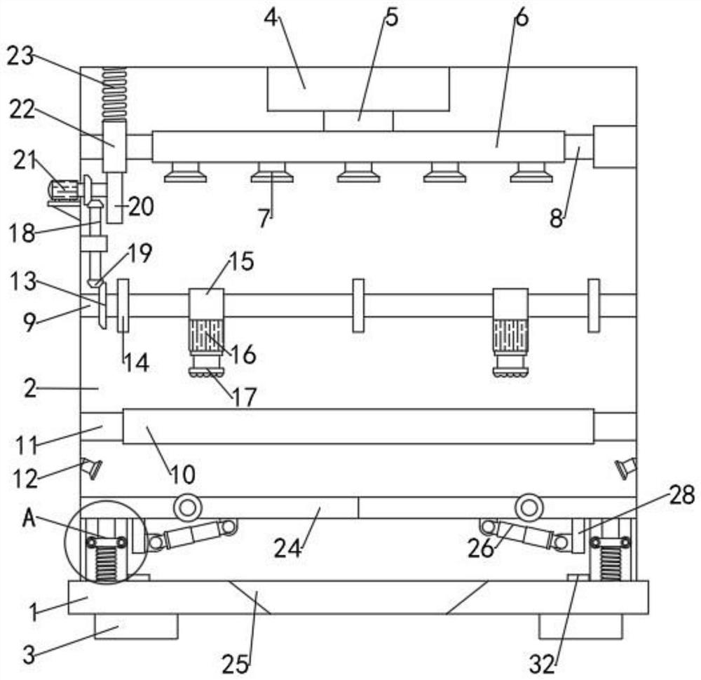
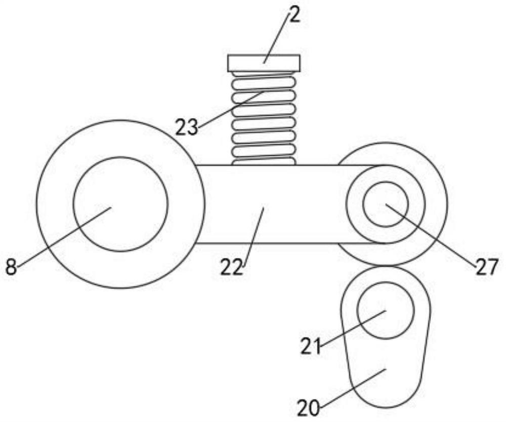
[0020] see Figure 1-4 , a debris cleaning device for numerical control machine tools, including a base 1, a cavity 2 is fixed on the upper end of the base 1, a workbench 10 is arranged on the inside of the cavity 2, and the two sides of the workbench 10 pass through several Evenly distributed connection bases 11 are connected to the cavity 2, and interlocking cleaning mechanisms and blowing mechanisms are arranged on the top of the workbench 10 to ensure the cleaning effect of debris; the blowing mechanisms include the first blower 4, the second A blower 4 is installed on the inner upper part of the cavity 2, the lower end of the first blower 4 communicates with the first substrate 6 via the delivery pipe 5, and the lower end of the first substrate 6 is evenly arranged with some air outlet pipes 7, and the first substrate 6 Both sides are installed and connected with the cavity 2 via the rotating shaft 8, wherein the rotating shaft 8 on one side is fixedly connected with a tr...

Embodiment 2

[0029] In order to facilitate the replacement of the cleaning brush 17 and ensure the cleaning effect, this embodiment is improved on the basis of Embodiment 1. The improvement is: the cleaning brush 17 is connected to the shaft of the cleaning motor 16 by a mating screw thread. In order to facilitate the disassembly and replacement of the cleaning brush 17, it is convenient to use.


PUM


Abstract

The invention discloses a debris cleaning device for a numerical control machine tool. The debris cleaning device comprises a base, a cavity is fixed to the upper end of the base, a workbench is arranged on the inner side of the cavity, and a sweeping mechanism and an air blowing mechanism which are in linkage are arranged above the workbench at intervals. According to the debris cleaning device for the numerical control machine tool, the sweeping mechanism and the air blowing mechanism which are in linkage are arranged, so that a cleaning brush conducts reciprocating sweeping along the workbench while an air outlet pipe swings to discharge air, and the cleaning effect is ensured; in addition, a second base plate has an induction effect, when the weight of debris accumulated on the secondbase plate is too large, a fixing base is attached to an induction switch, so that an electric telescopic rod opens the second base plate, and discharging is facilitated; a second air blower is arranged above the second base plate, so that the debris is prevented from being accumulated on the second base plate; and in addition, a buffer rod and a buffer spring are arranged between the second baseplate and the cavity, so that the second base plate is stable in operation, and the debris is convenient to clean.

Description

technical field [0001] The invention relates to the field of numerical control machine tools, in particular to a debris cleaning device for numerical control machine tools. Background technique [0002] CNC lathe is one of the most widely used CNC machine tools at present. It is mainly used for cutting the inner and outer cylindrical surfaces of shaft parts or disk parts, inner and outer conical surfaces with any cone angle, complex rotary inner and outer curved surfaces, and cylindrical and conical threads. It can also perform grooving, drilling, reaming, reaming and boring, etc.; CNC machine tools will produce a lot of metal debris during the production and processing of mechanical parts, and metal debris attached to the surface of the CNC machine tool will affect the normal operation of the machine tool. Some cleaning methods generally use a hair dryer or a brush for cleaning. Generally, the two cleaning methods cannot coexist and be linked together, so that the cleaning ...

Claims


Application Information

Patent Timeline
IPC IPC(8): B23Q11/00
CPCB23Q11/0042B23Q11/005
Inventor 丁志岩王磊魏海云马铭均杨朝举
Owner XINXIANG VOCATIONAL & TECHN COLLEGE
Why Eureka
Try Eureka