Catalytic cracking oil slurry treatment method and system thereof
A catalytic cracking oil slurry and catalytic cracking technology, which is applied in the direction of hydrocarbon oil treatment products, hydrocarbon oil treatment, hydrotreating process, etc., can solve the problems of difficult treatment of catalytic cracking oil slurry, and achieve the goal of prolonging the operation period and reducing the deposition rate Effect
- Summary
- Abstract
- Description
- Claims
- Application Information
AI Technical Summary
Problems solved by technology
Method used
Image
Examples
Embodiment 1-4
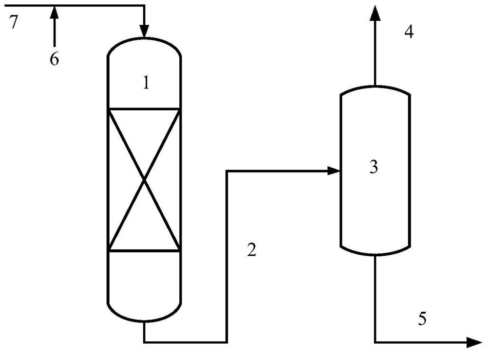
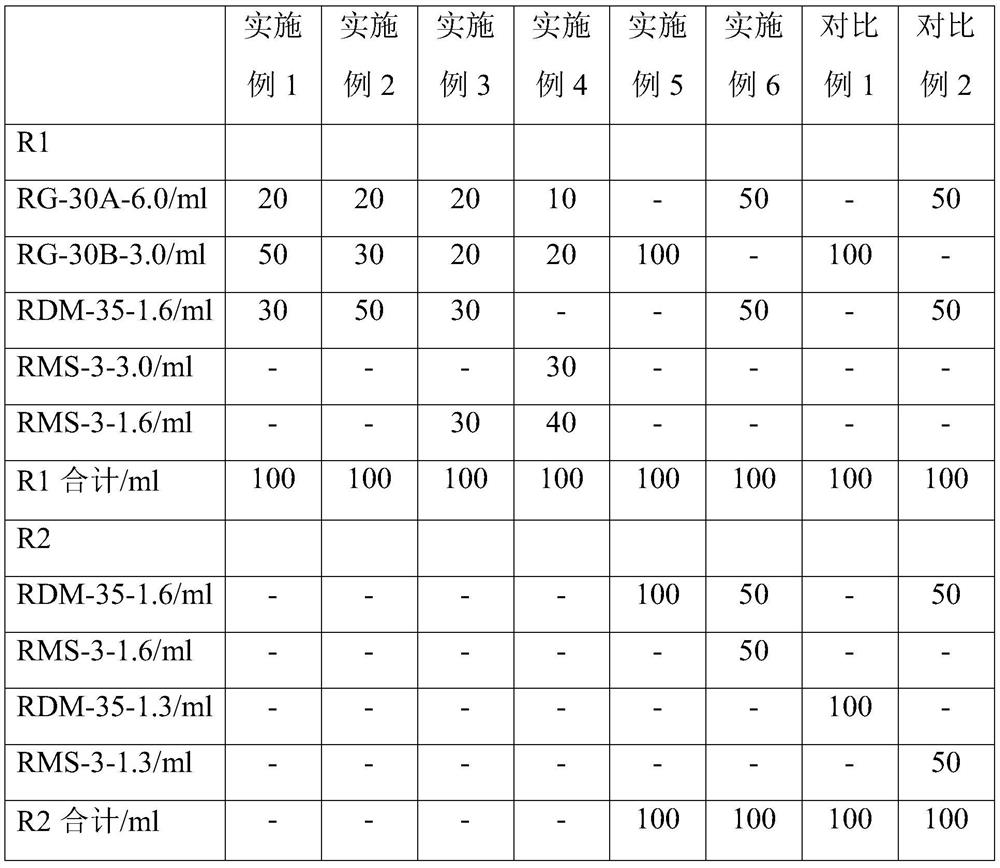
[0053] The catalytic cracking oil slurry and the hydrogen-containing gas enter the hydrogenation reaction zone of the hydroprocessing unit together. A fixed bed reactor is set in the hydrogenation reaction zone. In the presence of hydrogen, the catalytic cracking oil slurry and the catalyst in the fixed bed reactor The reaction is carried out by contact, and the reaction effluent enters the gas-liquid separation zone for separation to obtain hydrogen-rich gas and liquid phase stream. The catalyst loading gradation scheme in the hydrogenation reaction zone is shown in Table 2, the hydrogenation process conditions are shown in Table 3, and the properties of the catalytic cracking oil slurry and liquid stream are shown in Table 4. It can be seen from Table 4 that in the hydrogenation reaction zone of the catalytic cracking oil slurry, most of the sulfur is removed and the hydrogen content is appropriately increased, which obviously improves the properties of the catalytic cracking...
Embodiment 5
[0055] The catalytic cracking oil slurry and the hydrogen-containing gas enter the hydrogenation reaction zone of the hydroprocessing unit together, and two fixed-bed reactors connected in series are arranged in the hydrogenation reaction zone. In the presence of hydrogen, the catalytic cracking oil slurry is sequentially contacted with the catalysts in two fixed-bed reactors for reaction, and the reaction effluent enters the gas-liquid separation zone for separation to obtain hydrogen-rich gas and liquid phase stream. The catalyst loading gradation scheme in the hydrogenation reaction zone is shown in Table 2, the hydrogenation process conditions are shown in Table 3, and the properties of the catalytic cracking oil slurry and liquid stream are shown in Table 5. This embodiment carried out a stability test of 6000h. When the hydrotreating unit started to operate, the pressure drop of R-1 was 0.10MPa, and the pressure drop of R-2 was 0.12MPa. After the hydrotreating unit operat...
Embodiment 6
[0059]The catalytic cracking oil slurry and the hydrogen-containing gas enter the hydrogenation reaction zone of the hydroprocessing unit together, and two fixed-bed reactors connected in series are arranged in the hydrogenation reaction zone. In the presence of hydrogen, the catalytic cracking oil slurry is sequentially contacted with the catalysts in two fixed-bed reactors for reaction, and the reaction effluent enters the gas-liquid separation zone for separation to obtain hydrogen-rich gas and liquid phase stream. The catalyst loading gradation scheme in the hydrogenation reaction zone is shown in Table 2, the hydrogenation process conditions are shown in Table 3, and the properties of the catalytic cracking oil slurry and liquid stream are shown in Table 5. This embodiment carried out a stability test of 6000h. When the device started to operate, the pressure drop of R-1 was 0.09MPa, and the pressure drop of R-2 was 0.12MPa. -2 The pressure drop is 0.13MPa.
PUM
| Property | Measurement | Unit |
|---|---|---|
| particle diameter | aaaaa | aaaaa |
| pore size | aaaaa | aaaaa |
| particle diameter | aaaaa | aaaaa |
Abstract
Description
Claims
Application Information
 - R&D Engineer
- R&D Manager
- IP Professional
- Industry Leading Data Capabilities
- Powerful AI technology
- Patent DNA Extraction
Browse by: Latest US Patents, China's latest patents, Technical Efficacy Thesaurus, Application Domain, Technology Topic, Popular Technical Reports.
© 2024 PatSnap. All rights reserved.Legal|Privacy policy|Modern Slavery Act Transparency Statement|Sitemap|About US| Contact US: help@patsnap.com


