


Quick Research
Generate reliable direction feasibility study reports for your R&D in just a few steps.

Technical Q&A
Discover and master advanced knowledge NOW. Basics, ideas, possibilities, all at once.

Find Solutions
As an expert in R&D theories, this can generate solutions to your technical problems instantly.

Evaluate Feasibility
Analyze your overall solution with one click, know your potential R&D risks in advance.

Monitor Landscape
Get weekly tech updates, stay abreast of the latest tech innovations and key insights.
Porcelain bowl glazing device for ceramic process production
A technology of ceramic technology and porcelain bowls, which is applied in the field of glazing devices for porcelain bowls used in ceramic technology production, can solve problems such as unfavorable health and waste, and achieve the effect of facilitating glazing work and reducing material waste
- Summary
- Abstract
- Description
- Claims
- Application Information
AI Technical Summary
Problems solved by technology
Method used
Image

Examples
Embodiment 1
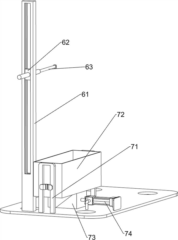
[0031] A kind of glazing device for porcelain bowls used in the production of ceramic crafts, such as Figure 1-5 As shown, it includes a bottom plate 1, a fixed plate 2, a driving mechanism 3, a lifting mechanism 4, a clamping mechanism 5, a balance mechanism 6 and an adjustable lifting box mechanism 7. The left rear side of the top of the bottom plate 1 is connected with a fixed plate 2, and the fixed plate 2 is respectively provided with a driving mechanism 3 and a lifting mechanism 4, the lifting mechanism 4 is connected to the driving mechanism 3 in transmission, the lifting mechanism 4 is provided with a clamping mechanism 5, and the bottom plate 1 is respectively provided with a balance mechanism 6 and an adjustable lifting box mechanism 7 , the balance mechanism 6 is in transmission connection with the clamping mechanism 5 .
[0032] The driving mechanism 3 includes a low-speed motor 31 and a power link 32. A low-speed motor 31 is installed on the rear side of the fixe...
Embodiment 2
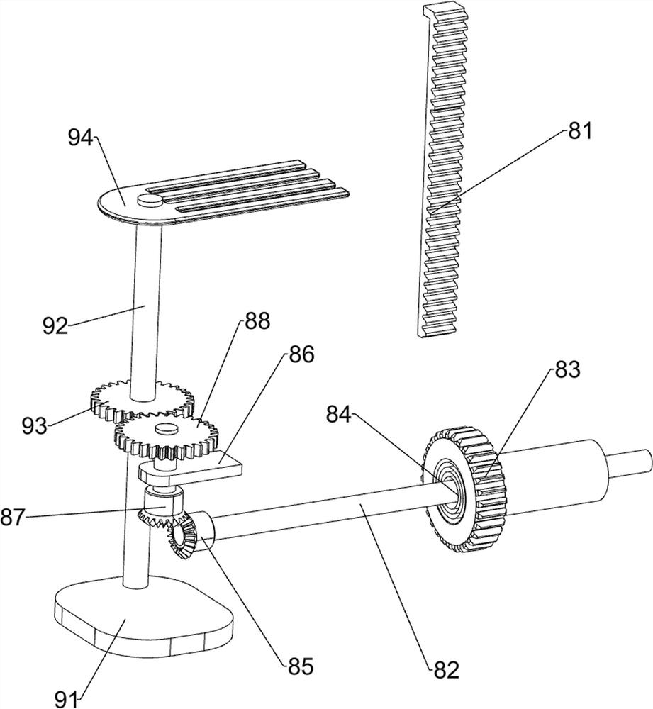
[0039] On the basis of Example 1, such as Image 6 with Figure 7 Shown, also comprise reset rotation mechanism 8, reset rotation mechanism 8 includes rack rack 81, rotating rod 82, transmission gear 83, scroll spring 84, first bevel gear 85, positioning plate 86, second bevel gear 87 and the first gear 88, the right side of the T-shaped connecting rod 51 is connected with a rack frame 81, and the front side of the top of the bottom plate 1 is connected with a positioning plate 86, and the positioning plate 86 is located on the right side of the hydraulic cylinder 74, between the positioning plate 86 and the fixed plate 2 Rotary type is connected with rotating rod 82, is connected with transmission gear 83 on the rotating rod 82, and transmission gear 83 cooperates with rack frame 81, is connected with scroll spring 84 between rotating rod 82 and fixed plate 2, and rotating rod 82 front end is connected with The first bevel gear 85 is rotatably connected with the second bevel...
Embodiment 3
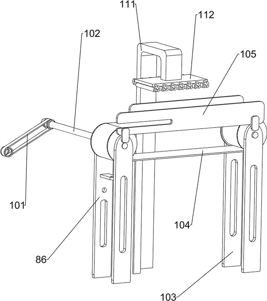
[0043] On the basis of Example 2, such as Figure 7 As shown, a transmission mechanism 10 is also included, and the transmission mechanism 10 includes a flat belt set 101, a transmission connecting rod 102, a top weight tripod 103, a pulley set 104 and a baffle plate 105, and the top right front side of the bottom plate 1 is connected with a top weight tripod 103, a belt pulley set 104 is connected in rotation between the top weight tripod 103 and the positioning plate 86, and a transmission connecting rod 102 is connected on the drive shaft on the left side of the belt pulley set 104, and the transmission connecting rod 102 is connected in rotation with the fixed plate 2, and the transmission A flat belt set 101 is connected between the connecting rod 102 and the power connecting rod 32, and a baffle plate 105 is connected between the front side of the top weight tripod 103 and the front side of the positioning plate 86, and the baffle plate 105 cooperates with the discharge p...
PUM
 Abstract
Description
Claims
Application Information
 - R&D Engineer
- R&D Manager
- IP Professional
- Industry Leading Data Capabilities
- Powerful AI technology
- Patent DNA Extraction
Browse by: Latest US Patents, China's latest patents, Technical Efficacy Thesaurus, Application Domain, Technology Topic, Popular Technical Reports.
© 2024 PatSnap. All rights reserved.Legal|Privacy policy|Modern Slavery Act Transparency Statement|Sitemap|About US| Contact US: help@patsnap.com