Soup spoon glazing device for ceramic soup spoon production
A technology of spoon and ceramics, which is applied in the field of spoon glazing equipment for the production of ceramic spoons, can solve problems such as low glazing efficiency, and achieve the effects of improving glazing efficiency and being easy to hang and remove.
- Summary
- Abstract
- Description
- Claims
- Application Information
AI Technical Summary
Problems solved by technology
Method used
Image


Examples
Embodiment 1
[0025] A spoon glazing equipment for the production of ceramic spoons, such as Figure 1-5 As shown, it includes a bottom plate 1, a glaze box 2, a bracket 3, a transport mechanism 4, a suspension mechanism 5, and a drive mechanism 6. The front side of the top of the bottom plate 1 is connected to the glaze box 2, and the right rear side of the top of the bottom plate 1 is installed with a bracket 3. , a transport mechanism 4 is installed on the glaze box 2, a suspension mechanism 5 is installed on the transport mechanism 4, a drive mechanism 6 is installed on the support 3, and the drive mechanism 6 is connected with the transport mechanism 4 in transmission.
[0026] Transport mechanism 4 includes support block 41, rotating shaft 42, belt pulley 43 and flat belt 44, and the front and rear sides of the top of glaze box 2 are connected with two support blocks 41 symmetrically. A rotating shaft 42 is connected, and a belt pulley 43 is connected on the rotating shaft 42 , and a ...
Embodiment 2
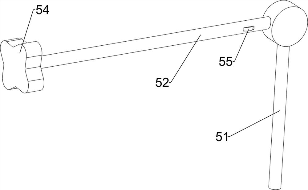
[0031] On the basis of Example 1, such as figure 1 and Figure 6 As shown, it also includes a push-out mechanism 7, and the push-out mechanism 7 includes a support rod 71, a slide rail 72 and a push block 73. A slide rail 72 is connected between them, and a push block 73 is slidably connected in the slide rail 72, and the push block 73 cooperates with the stop block 54.
[0032] The push block 73 can be moved forward, and the push block 73 can move forward to push the block 54 to move forward, so that the insertion rod 53 can be easily removed from the hollow round rod 52. When the insertion rod 53 is reinserted into the hollow round rod 52 When inside, make push block 73 move backwards and reset, so by pushing out mechanism 7 can be convenient to hang and take off soupspoon.
Embodiment 3
[0034] On the basis of Example 2, such as figure 1 and Figure 6As shown, a linkage mechanism 8 is also included, and the linkage mechanism 8 includes a first rail frame 81, a second rail frame 82, a second spring 83, a mounting plate 84, a spur gear 85, a rack 86, a first wedge block 87, The second wedge-shaped block 88, the third spring 89 and the connecting rod 810, the first rail frame 81 is connected to the left rear side of the top of the base plate 1, the left and right sides of the top of the glaze box 2 are connected to the second rail frame 82, and the top of the base plate 1 Connected with a mounting plate 84, the mounting plate 84 is located on the left side of the bracket 3, the upper part of the mounting plate 84 is rotatably connected with a spur gear 85, and the first rail frame 81 is slidingly connected with a rack 86, the rack 86 meshes with the spur gear 85 A second spring 83 is connected between the rack 86 and the first rail frame 81, a first wedge block ...
PUM
 Abstract
Description
Claims
Application Information
 - R&D
- Intellectual Property
- Life Sciences
- Materials
- Tech Scout
- Unparalleled Data Quality
- Higher Quality Content
- 60% Fewer Hallucinations
Browse by: Latest US Patents, China's latest patents, Technical Efficacy Thesaurus, Application Domain, Technology Topic, Popular Technical Reports.
© 2025 PatSnap. All rights reserved.Legal|Privacy policy|Modern Slavery Act Transparency Statement|Sitemap|About US| Contact US: help@patsnap.com