A post insulator glazing and polishing device and its working principle

A pillar insulator and polishing device technology, applied in the field of electric power equipment, can solve the problems affecting the smooth surface of the insulator, easy to form bulges, single device function, etc., and achieve the effects of improving polishing effect, reducing workload and reducing loss.

Active Publication Date: 2021-09-21
湖南太阳电力电瓷电器制造有限公司
View PDF0 Cites 0 Cited by
  • Summary
  • Abstract
  • Description
  • Claims
  • Application Information

AI Technical Summary

Problems solved by technology

Insulators play two basic roles in overhead transmission lines, namely supporting wires and preventing current from returning to ground. These two functions must be guaranteed. Insulators should not fail due to flashover breakdown caused by changes in the environment and electrical load conditions. , otherwise the insulator will lose its function, which will damage the service life and operating life of the entire line
[0003] Usually post insulators need to be polished and glazed before kiln molding to make the surface of post insulators smoother and improve the service life of post insulators. However, the existing glazing and polishing devices for post insulators still have deficiencies, mainly including the following: A few points: 1. The existing device has a single function and can only perform a single operation of polishing or glazing. The polishing precision is insufficient, and residual powder remains on the surface after polishing, and bulges are easy to form after glazing, which affects the smooth surface of the insulator. The existing device flies up the powder during polishing, which is not conducive to the environmental management of the working area and the physical and mental health of the operator. Three , The existing devices mostly use manual glazing with low work efficiency, and the mechanical glazing spraying angle is single and the glaze layer is uneven, making it difficult to control the quality of post insulators

Method used


Image

  • A post insulator glazing and polishing device and its working principle
  • A post insulator glazing and polishing device and its working principle
  • A post insulator glazing and polishing device and its working principle

Examples


Embodiment Construction

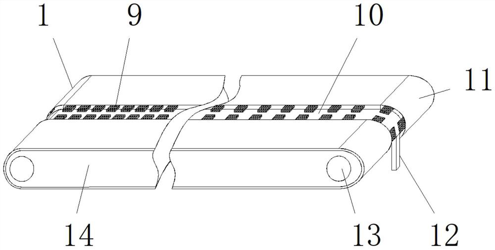
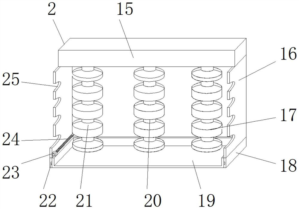
[0027] Embodiments of the present invention are described in detail below, examples of which are shown in the drawings, wherein the same or similar reference numerals denote the same or similar elements or elements having the same or similar functions throughout. The embodiments described below by referring to the figures are exemplary only for explaining the present invention and should not be construed as limiting the present invention.

[0028] In describing the present invention, it should be understood that the terms "center", "longitudinal", "transverse", "length", "width", "thickness", "upper", "lower", "front", " Orientation indicated by rear, left, right, vertical, horizontal, top, bottom, inside, outside, clockwise, counterclockwise, etc. The positional relationship is based on the orientation or positional relationship shown in the drawings, which is only for the convenience of describing the present invention and simplifying the description, rather than indicating ...


PUM


Abstract

The invention provides a post insulator glazing polishing device and its working principle, including a polishing device. The polishing device includes an upper top plate, a movable baffle, a fine polishing shaft, a lower bottom plate, a main body of a storage device, a middle polishing shaft, and a rough polishing shaft , sliding column, limit piece, screw rod and hole slot, the movable baffle is slidably connected to both sides of the lower end surface of the upper top plate, and the fine polishing shaft, middle polishing shaft and rough polishing shaft are rotatably connected to the upper top plate The lower end surface, the lower bottom plate is slidably connected to the lower end surface of the movable baffle, the main body of the storage device is slidably connected to the inside of the lower bottom plate through a sliding column, the stopper is fixedly connected to the inner side of the movable baffle, and the screw rod Rotationally connected in the limiter, the hole slot is set inside the movable baffle, and the front end of the polishing device is fixed in the middle with a touch display. The invention improves the production efficiency and quality of the post insulator, and at the same time Reduce the production cost of insulators.

Description

technical field [0001] The invention relates to the field of electric equipment, in particular to a post insulator glazing and polishing device and its working principle. Background technique [0002] Post insulators are special insulation controls that can play an important role in overhead transmission lines. In the early years, post insulators were mostly used on utility poles, and gradually developed into high-voltage wire connection towers where many suspended insulators are hung at one end. It is used to increase the creepage distance. It is usually made of silica gel or ceramics, called insulators. Insulators play two basic functions in overhead transmission lines, namely supporting wires and preventing current from returning to the ground. These two functions must be guaranteed. Insulators should not fail due to flashover breakdown caused by changes in the environment and electrical load conditions , otherwise the insulator will lose its function, which will damage ...

Claims


Application Information

Patent Timeline
Patent Type & Authority Patents(China)
IPC IPC(8): B28B11/08B28B11/04
CPCB28B11/044B28B11/048B28B11/0845
Inventor 杨涛
Owner 湖南太阳电力电瓷电器制造有限公司
Why Eureka
Try Eureka