
Turbine shell horizontal machining hydraulic clamp

A technology for hydraulic fixtures and turbine shells, applied in clamping, manufacturing tools, metal processing equipment, etc., can solve problems such as waste of resources, increase clamping time, and long production takt time, and achieve the effect of reducing occupancy and improving productivity.

Pending Publication Date: 2021-02-09
KUNSHAN YONG XIANG PRECISION MACHINERY
View PDF0 Cites 0 Cited by
  • Summary
  • Abstract
  • Description
  • Claims
  • Application Information

AI Technical Summary

Problems solved by technology

[0004] The object of the present invention is to provide a kind of turbine casing horizontally adding hydraulic clamp, to solve the above-mentioned background technology through the clamp on the turbine casing horizontally adding hydraulic clamp can play the role of positioning, support and clamping, but existing The production process of the product is more, the number of clamping is more, and it takes up more equipment. The multiple sequential processing of the product increases the clamping time, takes up more equipment, and increases the non-processing time. The cumulative production tact time of a single product is compared. Long, and a single piece is produced every time, the efficiency is relatively low, and resources are wasteful

Method used


Image

  • Turbine shell horizontal machining hydraulic clamp
  • Turbine shell horizontal machining hydraulic clamp
  • Turbine shell horizontal machining hydraulic clamp

Examples


Embodiment Construction

[0021] The following will clearly and completely describe the technical solutions in the embodiments of the present invention with reference to the accompanying drawings in the embodiments of the present invention. Obviously, the described embodiments are only some, not all, embodiments of the present invention. Based on the embodiments of the present invention, all other embodiments obtained by persons of ordinary skill in the art without making creative efforts belong to the protection scope of the present invention.

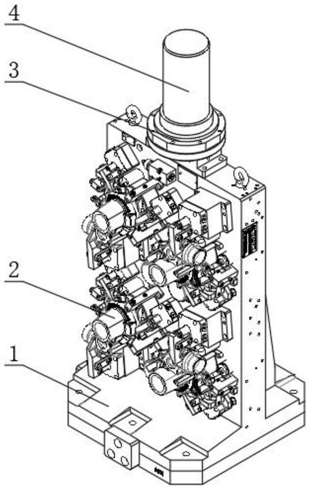
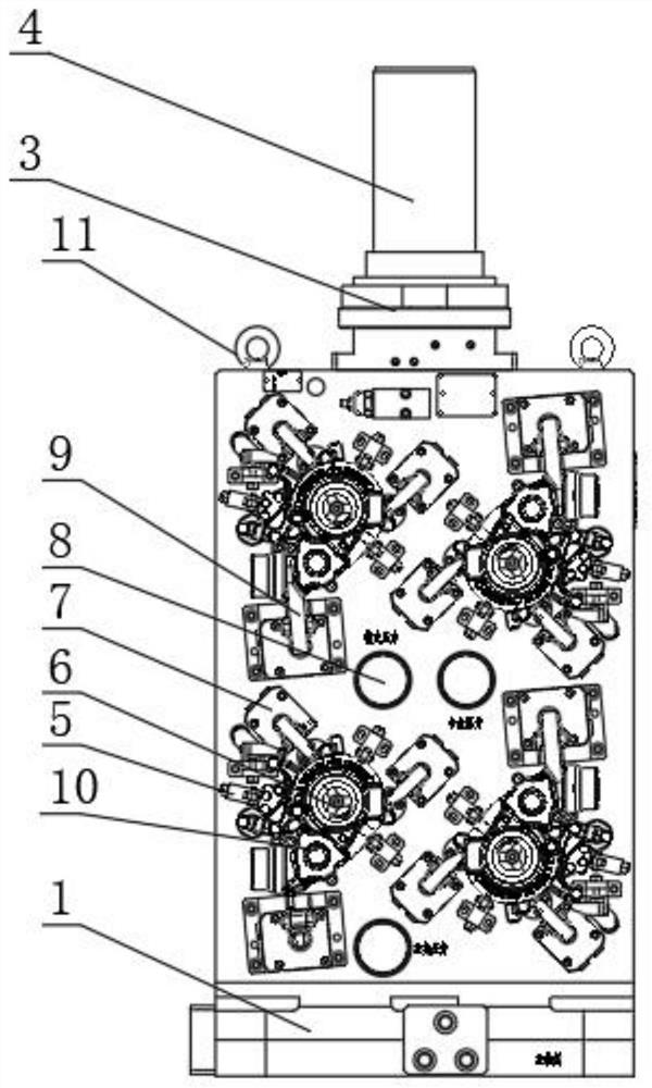
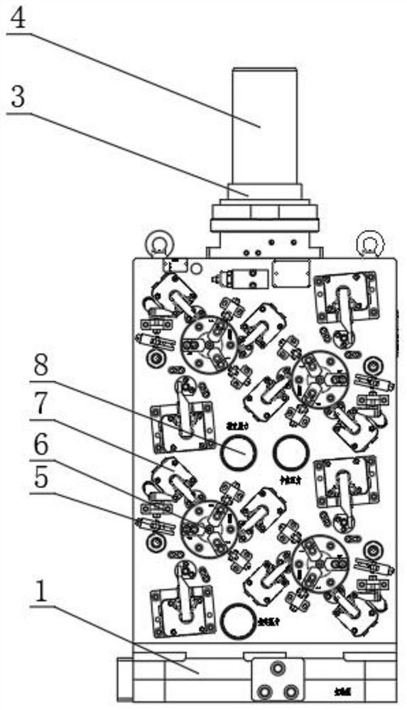
[0022] see Figure 1-6 , the present invention provides a technical solution: a hydraulic clamp for horizontal turbine casing, including a double-sided stand 1 and an oil separation adapter plate 3, the double-sided stand 1 is made of stainless steel, this design greatly improves the Durability and stability during use, the surface of the double-sided stand 1 is polished, so that the design is smoother when in use, and the middle part of the top of the double-...


PUM


Abstract

The invention discloses a turbine shell horizontal machining hydraulic clamp. The turbine shell horizontal machining hydraulic clamp comprises a double-sided vertical base and an oil distribution adapter plate, wherein the oil distribution adapter plate is installed in the middle of the top end of the double-sided vertical base, the top end of the oil distribution adapter plate is sleeved with anoil distributor, pull rings are arranged at the left side and the right side of the top end of the double-sided vertical base, and clamp devices are arranged at the front end of the double-sided vertical base. When in use, workpieces are manually put into the clamp, elastic side jacking mechanisms and self-made piston rods drive chucks to center the workpieces, angular oil cylinders push the workpieces tightly, main pressing oil cylinders press the workpieces tightly, and auxiliary supports jack up the workpieces. A machine tool start machining, so that the problems of single-station production, low efficiency and low output rate of the workpieces are solved, the occupancy rate of equipment can be reduced, and the use performance of the equipment is fully exerted; and loading is performedat the outer side during inner side machining, so that the productivity is improved, and thus on the premise that the workpieces are firmly clamped, the production efficiency is improved, and unstablefactors generated in the production process are reduced.

Description

technical field [0001] The invention belongs to the related technical field of clamps, and in particular relates to a hydraulic clamp for horizontal loading of a turbine shell. Background technique [0002] The hydraulic fixture is a fixture that uses hydraulic components instead of mechanical parts, and realizes automatic positioning, support and clamping of the workpiece through hydraulic control. It has the advantages of large clamping force, reliable clamping, stable operation, and convenient use. It is currently widely used in CNC machine tools, machining centers, and automated production lines. By assembling the selected hydraulic components and the designed mechanical parts, the required fixture can be obtained. The hydraulic fixture can ensure the accurate positioning and firm clamping of the workpiece at the specified position, and can reduce the machining process through the floating support. The vibration and deformation of the machine can also be used to automat...

Claims


Application Information

Patent Timeline
Patent Type & Authority Applications(China)
IPC IPC(8): B23Q3/08
CPCB23Q3/082B23Q3/062
Inventor 李宋英
Owner KUNSHAN YONG XIANG PRECISION MACHINERY
Learn More